Chapter 8 Hardware Reference
© 2017 Harmonic Inc. All rights reserved. 236 Harmonic MediaGrid Release 4.1
ContentBridge 2010F
Rear Panel Components
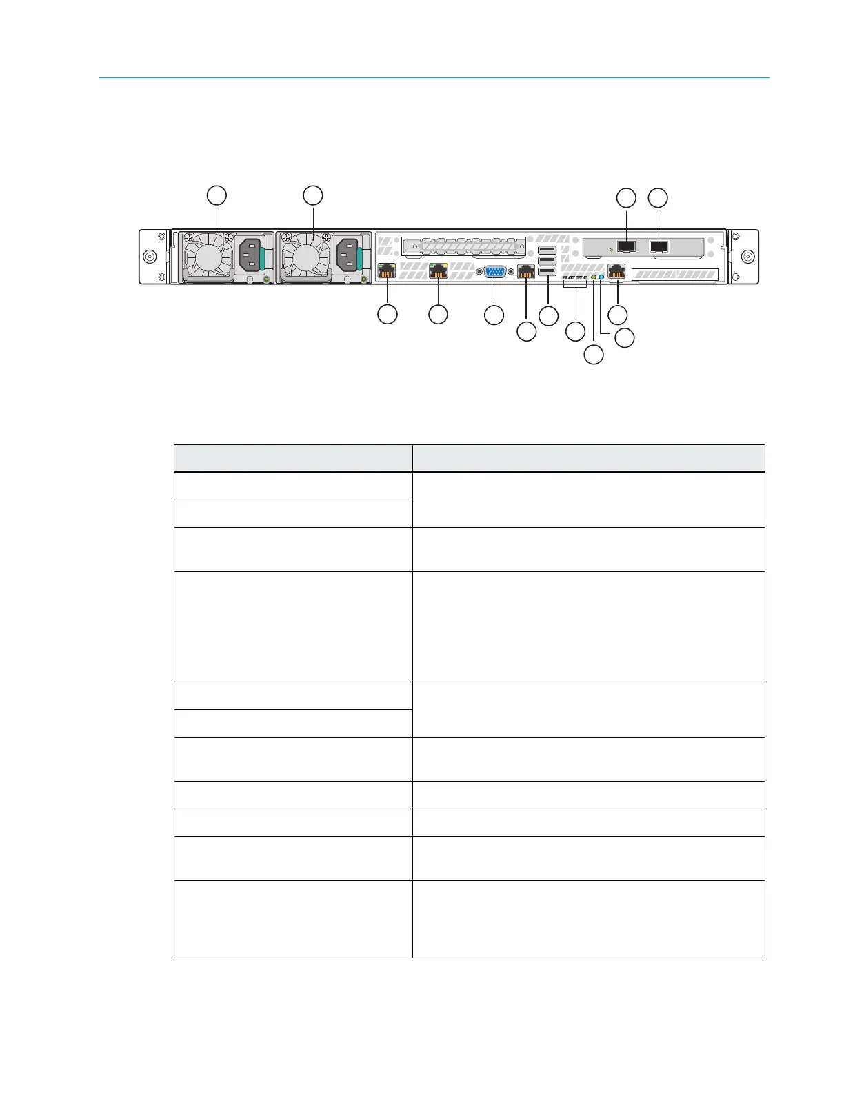
Figure 8–15 and Table 8–15 describe the rear panel view of the ContentBridge 2010F
Figure 8–15: Rear View of ContentBridge 2010F
Table 8–15: ContentBridge 2010F Rear Panel Components
Indicator, Button, or Connector Description
1. Power supply 1 Dual redundant power supplies provide
power to the
system.
2. Power supply 2
3. 10 Gigabit Ethernet connector 3
Use to connect the ContentBridge 2010F to the
network switch.
4. 10 Gigabit Ethernet connector 2 Use to connect the ContentBridge 2010F to the
network switch.
The Link light does not appear until the Configuration
Assistant is completed for the ContentBridge. Refer to
About Harmonic MediaGrid Configuration for more
information.
5. Gigabit Ethernet connector 0 Use to connect two High Bandwidth ContentBridges in
a high availability pair.
6. Gigabit Ethernet connector 1
7. Video connector Use to connect a monitor to the system (for
maintenance only).
8. RJ-45 serial port Serial cable is not provided.
9. USB ports (3) Used for maintenance purposes only.
10. Diagnostic LEDs For Service only. LEDs are located on the back edge of
the
server board.
11. System Status LED Located on the back edge of the server board, this
LED match
es the state of the System Status LED on
the front Control Panel. Refer to Table 8–13 for a
description of each LED state.
2
1
5
3
4
6
7
8
9
10
11
12
13