Appendix A Legacy Hardware Platforms
© 2017 Harmonic Inc. All rights reserved. 306 Harmonic MediaGrid Release 4.1
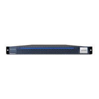
ContentDirector 1000E and High Performance ContentDirector 2000B
Drive Status LEDs
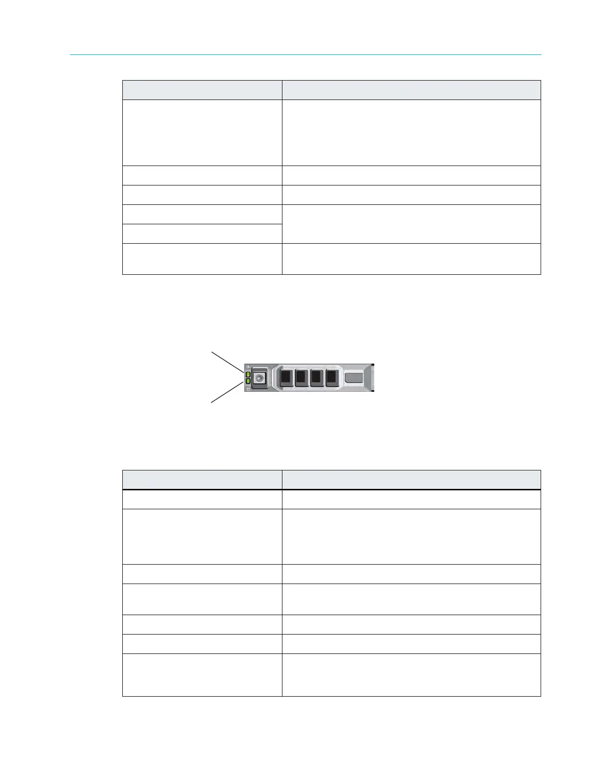
Figure 9–5 and Table 9–6 describe the drive indicators and their functions.
Figure 9–5: ContentDirector Drive Indicators
Table 9–6: Drive-status Indicator Pattern (RAID Only)
5. LCD display Displays system ID, status information, and system error
mess
ages. The LCD lights blue during normal system
operation. The LCD lights amber when the system needs
attention, and the LCD panel displays an error code
followed by descriptive text.
6. USB connectors Use to connect the front bezel.
7. Optical drive Use for software installation.
8. Hard drive 0 Refer to Table 9–6 for a description of the indicator codes.
9. Hard drive 1
10. Solid state drive Available only in the High Performance ContentDirector
2000B.
Drive-status Indicator Pattern Condition
Blinks green two times per second Identify drive/preparing for removal
Off Drive ready for insertion or removal
Note: The drive-status indicator remains off until all hard
drives are initialized after system power is applied. Drives
are not ready for insertion or removal during this time.
Blinks green, amber, and off Drive predicted failure
Blinks amber four times per
second
Drive failed
Blinks green slowly Drive rebuilding
Steady green Drive online
Blinks green three seconds,
amber thr
ee seconds, and off six
seconds
Rebuild aborted
Indicator, Button, or Connector Description
Drive-activity Indicator (green)
Drive-status Indicator (green and amber)