2-30 888-2629-200 10/6/10
WARNING: Disconnect primary power prior to servicing.
Section 2 Installation
Maxiva ULX COFDM Series
Table 2-8 Customer I/O panel Connections for Exciter B
STEP 2 Connect sample cables from Forward and Reflected directional
couplers (at the system output, after the filter), from reject load
directional couplers, and from the PA RTAC to the customer I/O
panel at the top of the cabinet. These samples are listed in Table 2-9. If
necessary, these samples will be calibrated using the GUI after initial
turn-on (see
"5.8 Power Calibrations" on page 5-15). These sample
cables are not supplied since the required length is determined at each
site.
NOTE:
Refer to the Apex M2X technical manual for RTAC sample levels.
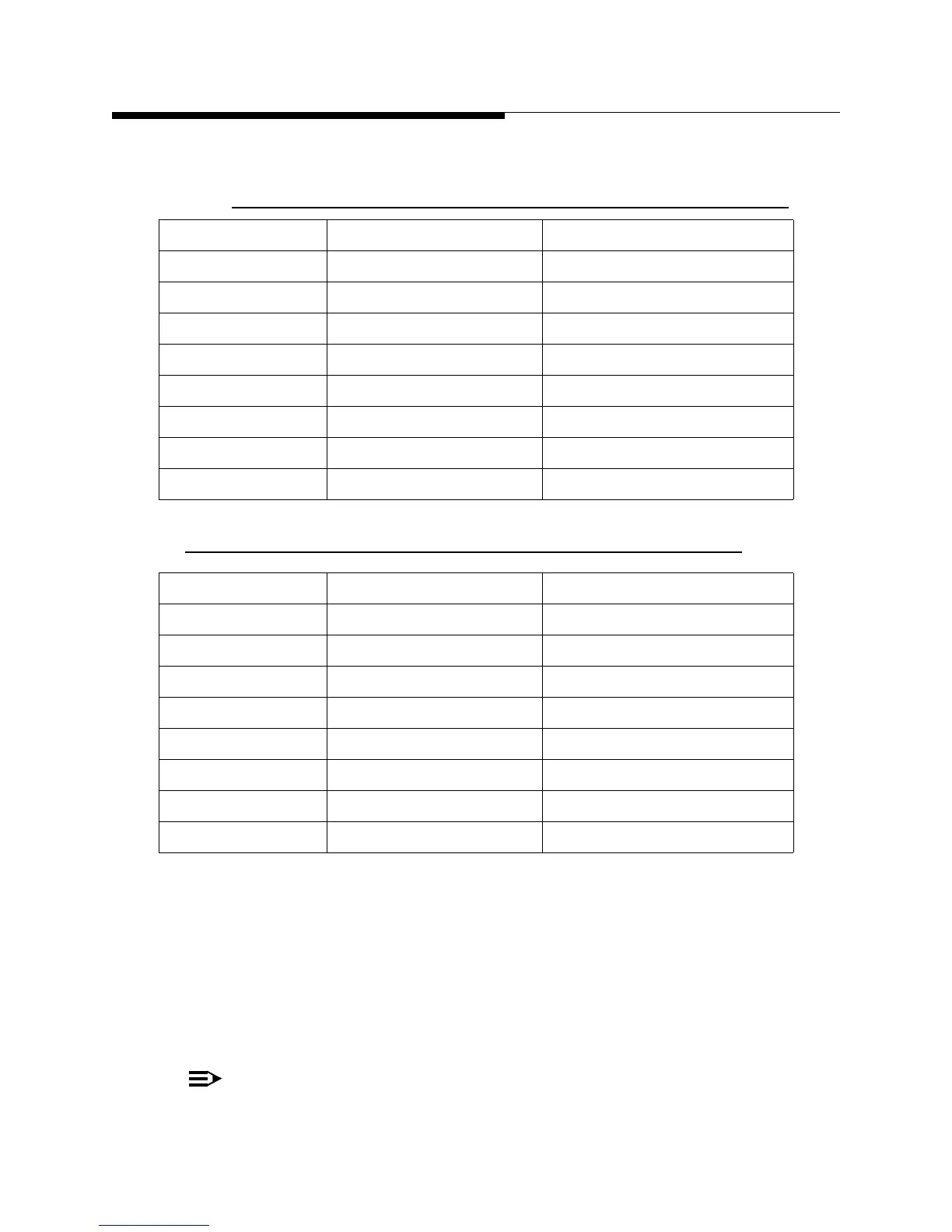
Table 2-7 Customer I/O panel Connections for Exciter A
Jack Connector Label
J1 SMA - 50Ω GPS (antenna)
J2 BNC - 50Ω 1PPS
J3 BNC - 50Ω 10 MHZ
J4 BNC - 75Ω ASI HP1
J5 BNC - 75Ω ASI LP-1
J6 BNC - 75Ω 310 HP-2
J7 BNC - 75Ω 310 LP-2
J8 BNC - 75Ω TS Loop Out
Jack Connector Label
J1 SMA - 50Ω GPS (antenna)
J2 BNC - 50Ω 1PPS
J3 BNC - 50Ω 10 MHZ
J4 BNC - 75Ω ASI HP1
J5 BNC - 75Ω ASI LP-1
J6 BNC - 75Ω 310 HP-2
J7 BNC - 75Ω 310 LP-2
J8 BNC - 75Ω TS Loop Out
 Loading...

