10/6/10 888-2629-200 2-31
WARNING: Disconnect primary power prior to servicing.
Section 2 Installation
Maxiva ULX COFDM Series
NOTE:
J23 is the WAN/LAN connector.
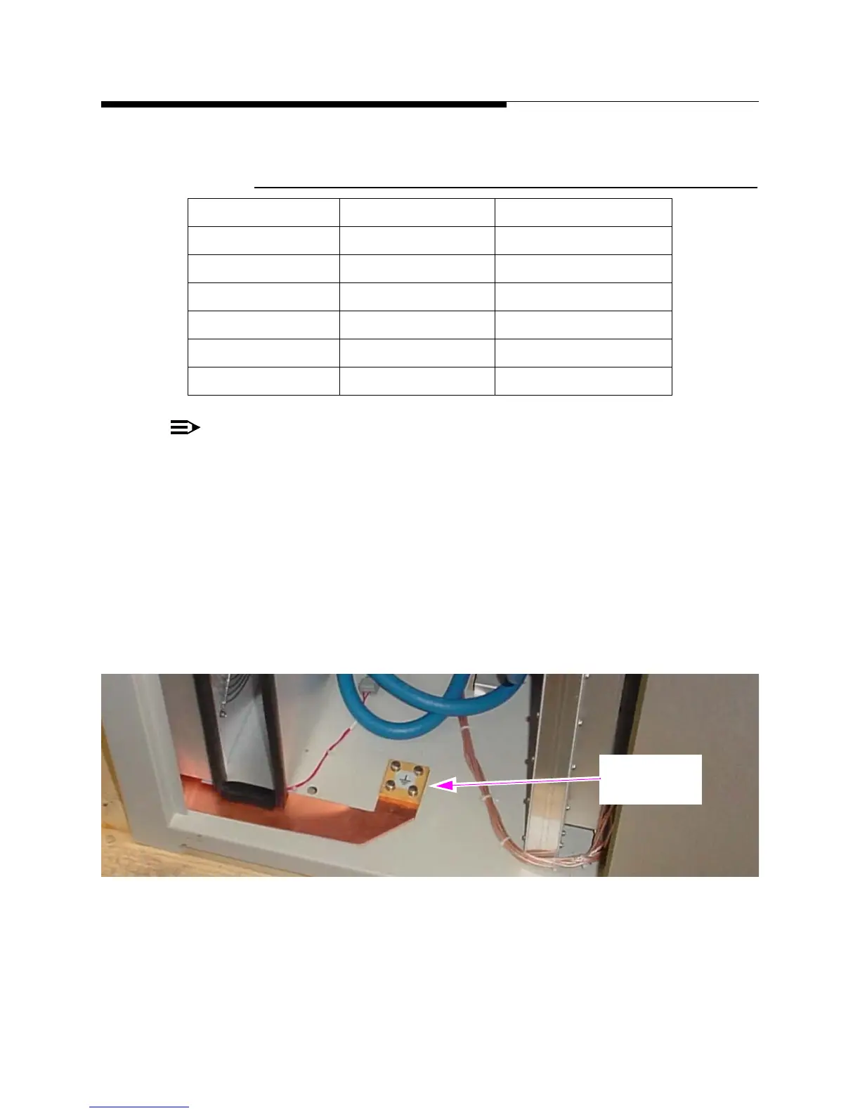
STEP 3 Connect a ground strap from each cabinet’s E1 block (located at the
bottom, rear, center inside each cabinet) to the station ground. The
E1 block is shown in Figure 2-10. A roll of copper strapping is shipped
with the transmitter. Roll this strap out and attach it beneath the cabinet
ground block in the cabinet and to station ground on the other. If any
additional copper strap is needed, it must be at least 5cm wide and
0.5mm thick.There is an additional E1 block located on top of each
cabinet (see Figure 2-9) for additional grounding as needed.
Figure 2-10 Cabinet Ground Connection Block
Table 2-9 RF Samples Connections on Customer I/O Panel
Jack Connector Label
J17 N - 50 Ω SYS FWD
J18 N - 50 Ω SYS REF
J19 N - 50 Ω REJECT 1
J20 N - 50 Ω REJECT 2
J21 N - 50 Ω REJECT 3
J22 N - 50 Ω PA RTAC
Cabinet
Ground
 Loading...

