2-56 888-2629-200 10/6/10
WARNING: Disconnect primary power prior to servicing.
Section 2 Installation
Maxiva ULX COFDM Series
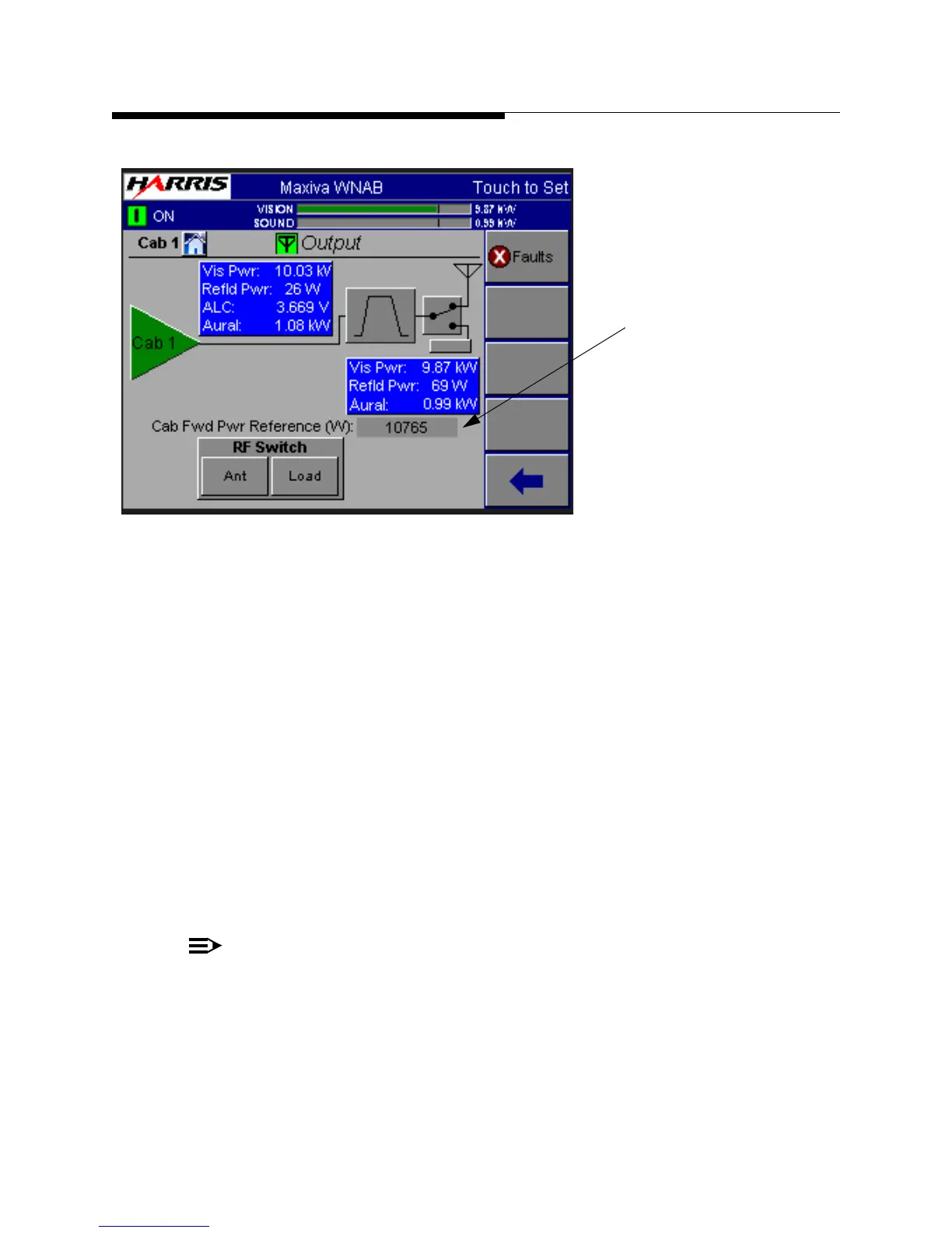
Figure 2-17 Output Screen
STEP 9 Slowly bring up the transmitter power (see Output screen) by
pressing the RAISE button on front panel to the nominal value, as
indicated by the bar graphs. Monitor the cabinet forward and reflected
powers, as well as the VSWR reading. A large VSWR (above 1.1) is
indicative of a bad RF connection to the test load.
STEP 10 Adjust cabinet phasing (in multi-cabinet systems) to reduce reflected
power into the cabinet combiner reject loads. Inter-cabinet phasing is
accomplished via the GUI to adjust the preamplifier modules in each
cabinet relative to the other cabinets to reduce reflected power to the
common reject loads.
STEP 11 Verify that the transmitter meter readings are close to the factory
test data meter readings, especially all of the current and voltage
readings.
NOTE:
Rebias of the FET’s in the PA modules is not required in this transmitter. They
have been pretested at the factory to minimize drift.
STEP 12 Verify power output on GUI corresponds with the external power
meter. If there is a discrepancy, perform the power calibration procedure
"5.8 Power Calibrations" on page 5-15 in this manual.
Cabinet power will
go to this level
if TCU set to Auto
 Loading...

