Modules and transducers
108 I3031-14.0 HBM: public Quantum
X
8.5.1 MX430B pin assignment
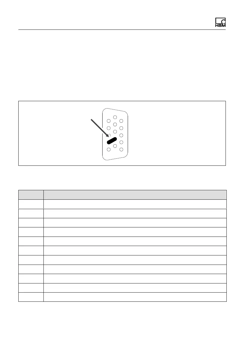
So that insertion or removal of a transducer connection
can be unmistakably identified, Pin 4 and Pin 9 in the
connector plug must be bridged! If this bridge is missing,
no measurement values will be recorded at the connec
tion!
1
4
5
11
15
Bridge
Fig. 8.7 Pin arrangement of connector plug, view from the
solder side
Pin Connector
1 TEDS (+)
2 Bridge excitation voltage (-)
3 Bridge excitation voltage (+)
4 Always connect with Pin 9! (Plug-in detection)
5 Measurement signal (+)
6 TEDS (-)
7 Sense lead (-)
8 Sense lead (+)
9 Signal ground
10 Measurement signal (-)
11 Active sensor supply 5 ... 24 V , (-)