11 Commissioning
PHLOX - Ignition Control System 87
The position of the speed measuring wheel gap must be determined exactly. The ignition
TDC of the cylinder selected first (cylinder A1, TDC is equivalent to 0° crankshaft angle)
is to be used as a reference point. All distances (including that of the speed measuring
wheel gap) are specified in degrees of crankshaft angle before the compression TDC of
cylinder A1.
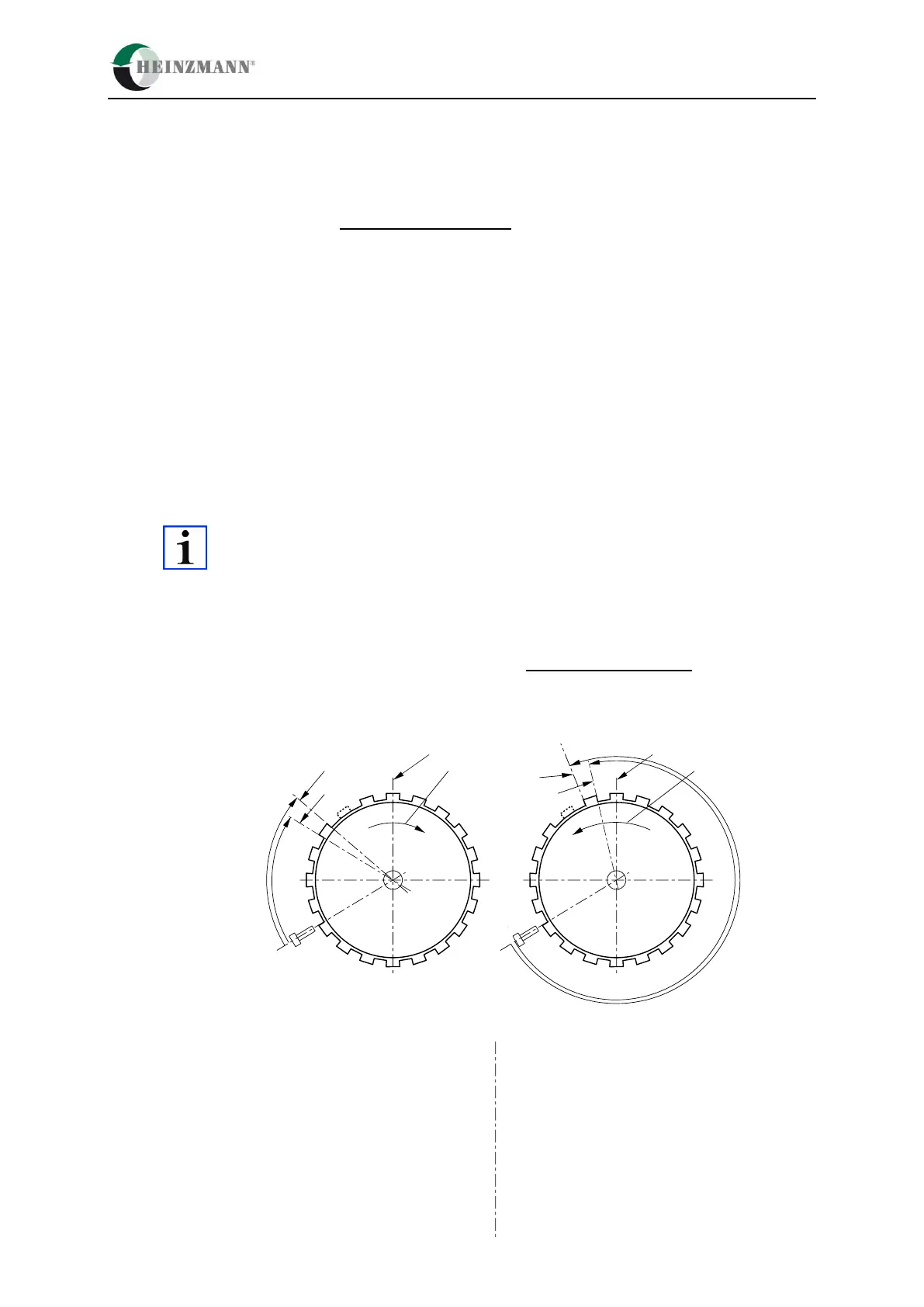
Procedure to determine the distance (see following images):
1. The crankshaft is rotated into a position where cylinder A1 is exactly at TDC (ignition TDC).
2. For Hall Pick-ups: The distance between the centre of the sensor and the beginning
or the end (depending on Par. 4024) of the first tooth after gap is measured by degrees of
crankshaft starting from the sensor in the direction in which the engine rotates.
For Inductive Pick-ups: The distance between the centre of the sensor and the centre of
the first tooth after gap is measured by of degrees crankshaft starting from the sensor in the
direction in which the engine rotates.
The following pictures make use of a measuring wheel with single tooth gap.
The setup remains exactly the same of a measuring where a wheel with double
tooth gap is used
Attention: angles must be converted into degrees of crankshaft.
Figure 15: Crankshaft angle Hall pick-ups
Ignition TDC of cylinder A1
Rotational direction of engine
Ignition TDC of cylinder A1
Rotational direction of engine
α = Distance of
sensor to gap
α = Distance of
sensor to gap

 Loading...