6 Installation
PHLOX II Ignition Control System 21
6.2 Pin assignment
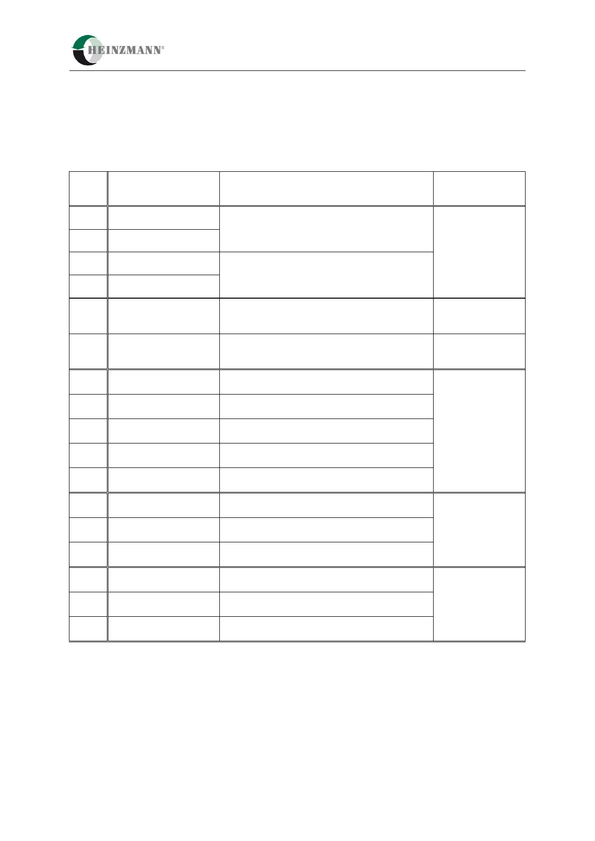
6.2.1 PHLOX II - IC8/12/16 – Pin assignment Connector X1
Digital / PWM input 1
(high- or low-side configurable)
Digital / PWM output 1 (low-side up to 1A).
Digital / PWM input 2
(high- or low-side configurable)
Digital / PWM output 2 (low-side up to 1A).
Sensor supply (configurable 5V/ 24V)
AI (C/V):
Differential analogue
input, configurable:
0 ... 5 V or
0 ... 25 mA
Sensor signal
(configurable 0 ... 25 mA / 0 ... 5 V)
Sensor supply ground (POW_0V)
CAN- Interface
ISO/DIS 11898
(CAN2.0B)
CAN ground and CAN cable shield connection
CAN2 /
Modbus Interface
(option)
ISO/DIS 11898
(CAN2.0B)
RS485
(Modbus)
CAN2 / Modbus ground and
CAN2 / Modbus cable shield connection

 Loading...