ENGINE (J05E)/TROUBLESHOOTING2–90
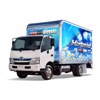
1. Use the electrical tester to measure the resistance between the
terminals in the CAN H-line and L-line on J/C_CAN1 (22P) side,
viewed from J/C_CAN1 (10P).
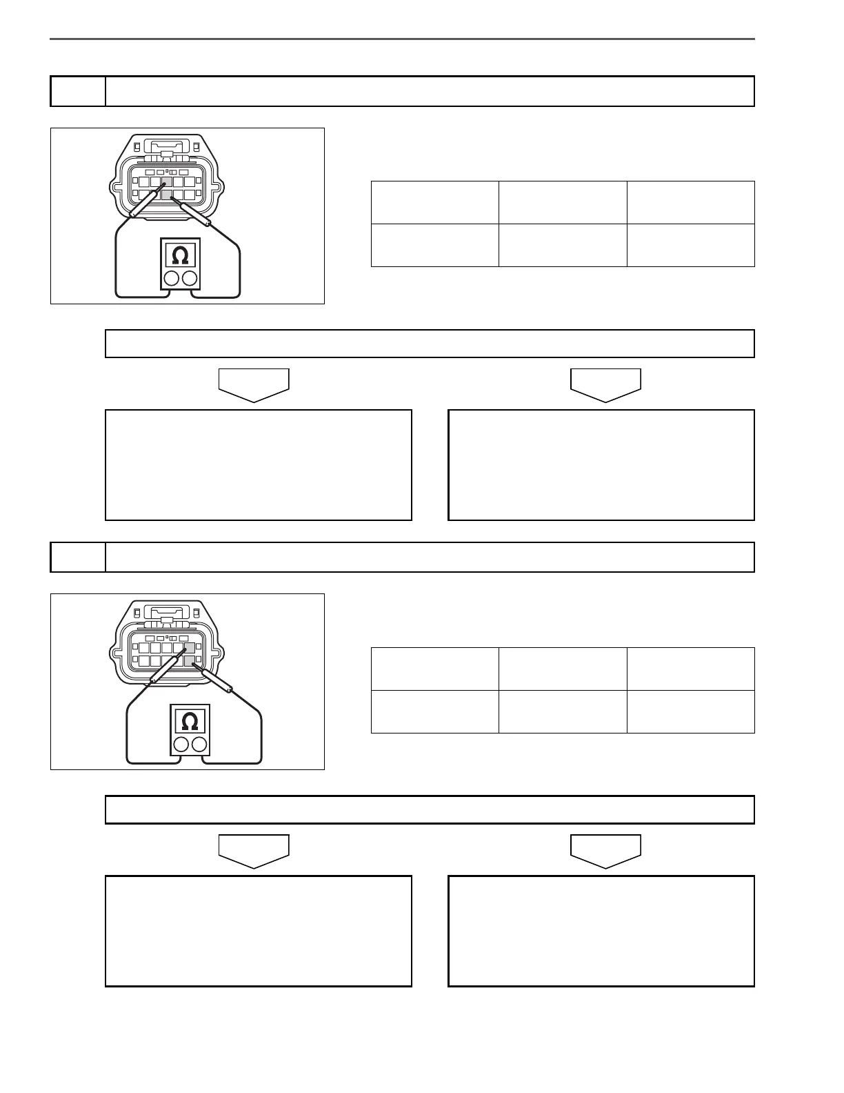
1. Use the electrical tester to measure the resistance between the
terminals in the CAN H-line and L-line on J/C_CAN1 (10P) side,
viewed from HV PCU.
4
Check harness in CAN bus line between J/C_CAN1 (10P) and J/C_CAN1 (22P) (Failure Site 5)
Measurement
conditions
Tester
connections
Standard values
Starter key: LOCK
J/C_CAN1 (10P):
3rd – 8th
110 – 130
Do the measurements meet the standard value?
Go to step 5. CAN bus line disconnection between CAN_J/
C2 and vehicle control ECU
Repair or replace the harness.
Perform After-inspection work. (Clear all past
DTC. Check no DTC is stored after test
drive.)
5
Check harness in CAN bus line between HV PCU and J/C_CAN1 (10P) (Failure Site 4)
Measurement
conditions
Tester
connections
Standard values
Starter key: LOCK
J/C_CAN1 (10P):
5th – 10th
110 – 130
Do the measurements meet the standard value?
Connect the J/C_CAN1 (10P) connector, and
go to step 6.
CAN bus line disconnection between HV
PCU and J/C_CAN1 (10P)
Repair or replace the harness.
Perform After-inspection work. (Clear all past
DTC. Check no DTC is stored after test
drive.)
 Loading...