ENGINE (J05E)/TROUBLESHOOTING 2–5
1. ILLUSTRATION OF CONNECTOR AND MEASUREMENT ON TERMINAL
2
3
1
5
6
4
2
1
3
5
4
6
LOCK
TO BE CONNECTED
MALE
CONNECTOR
FEMALE
CONNECTOR
FEMALE
CONNECTOR
231
564
MALE
CONNECTOR
213
546
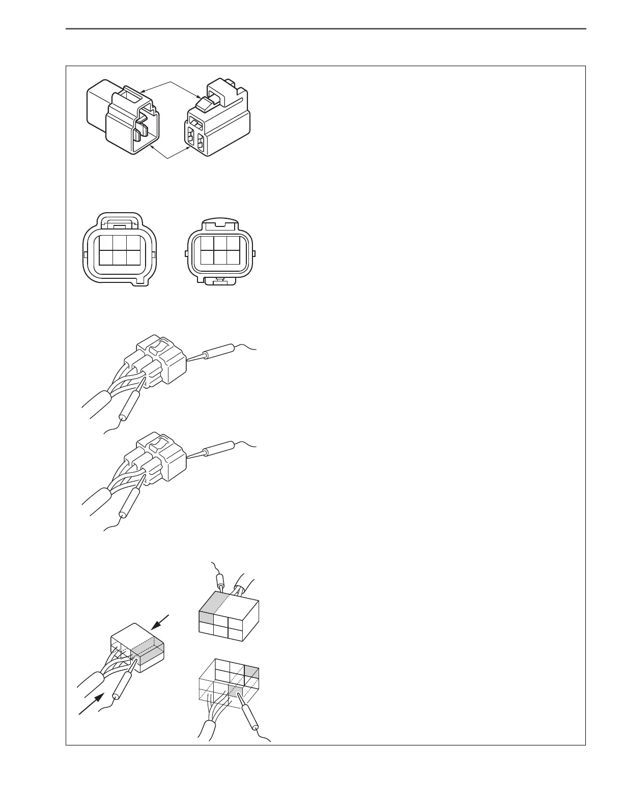
ILLUSTRATION OF CONNECTOR
NUMBERING OF CONNECTOR TERMINALS
PRECAUTIONS FOR TERMINAL MEASUREMENT
ILLUSTRATION OF CONNECTOR AND
MEASUREMENT SURFACE
VIEW A
VIEW B
B
A
The illustration of a connector contained in this document
represents an image of a connector with its lock positioned
on top as viewed from the connecting face.
The terminals are symmetrically numbered (symmetrically
reversed numbering) as viewed on the connecting faces of a
pair of connectors.
The terminal #1 is located at the top right corner of a male
connector and at the top left corner of a female connector
respectively in this document.
Unless otherwise specified in this document, the illustration
of a connector represents an image of a connector as viewed
from the connecting face. A test probe must access the back
face of a connector.
However, some types of connector do not allow a test probe
to contact with the back face such as a waterproof connector.
In such case, a test probe may be allowed to access the front
face of a connector but a special care must be used to avoid
a risk of damage in terminals.
As to a connector that is designed to use the signal check
harness for terminal measurement, do not place a test probe
directly onto the front or back face. Use a contact box of the
connected signal check harness to take measurement on
terminals.
The illustration of a connector contained in this document
represents an image of a connector as viewed from the
connecting face. For example, the terminal #1 of a female
connector is located at the top left corner of a connector as
viewed from the connecting face.
In actual measurement on the terminal #1 of a female
connector, a test probe must be placed onto the top right
corner on the back face of a connector.
WATERPROOF CONNECTOR
INCORRECT
INCORRECT
CORRECT
CORRECT
 Loading...