ENGINE (J05E)/TROUBLESHOOTING2–218
1. Set the starter key to the "LOCK" position.
2. Disconnect the boost pressure sensor connector.
3. Connect the signal check harness to the engine ECU vehicle side
harness. (Do not connect harness to the ECU.)
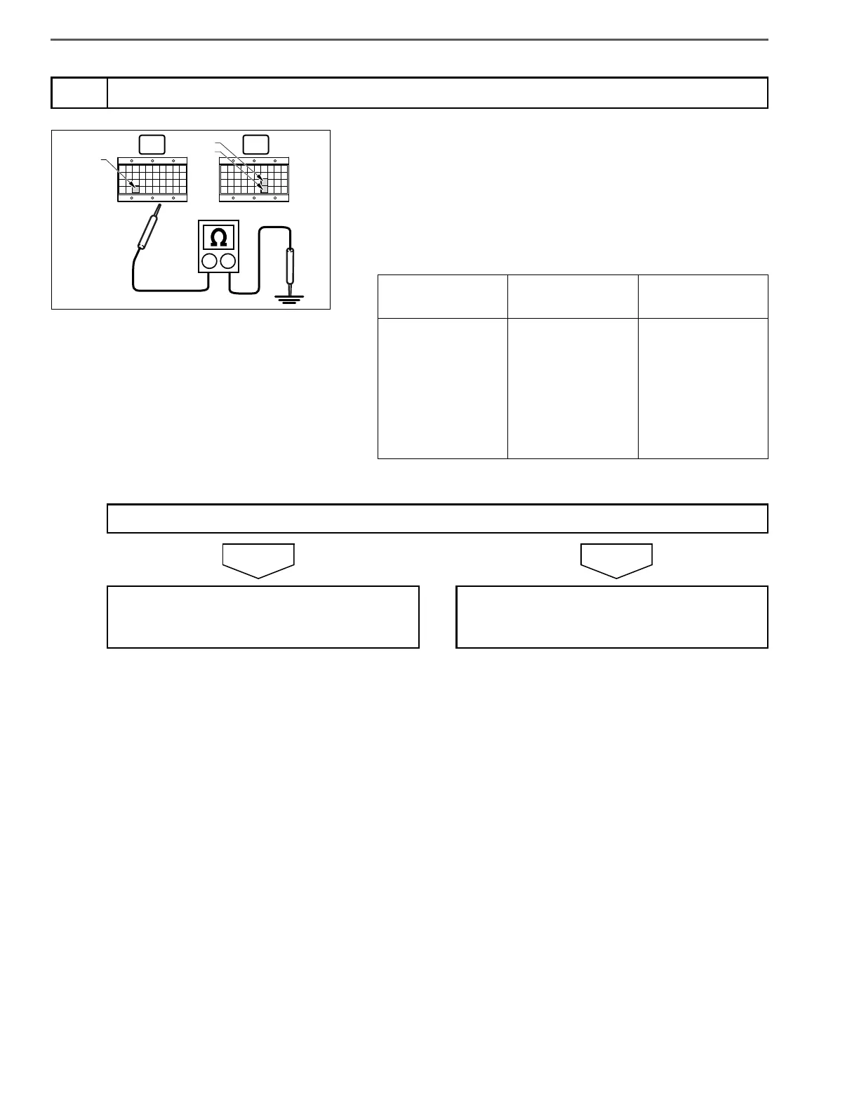
4. Use the electrical tester to measure the resistance between each
terminal in the engine ECU (signal check harness) and ground.
3
Inspect for short-circuits in wire harness of boost pressure sensor
Measurement
conditions
Tester
connections
Standard values
Starter key: LOCK
Engine ECU (sig-
nal check har-
ness)
VC2 (E33) –
Ground
PIM (E67) –
Ground
E4 (E77) – Ground
Do the measurements meet the standard value?
Go to step 4. Repair or replace the harness.
Perform "After-inspection work" of INFOR-
MATION section.
 Loading...