ENGINE (J05E)/TROUBLESHOOTING2–572
1. Set the starter key to the "LOCK" position.
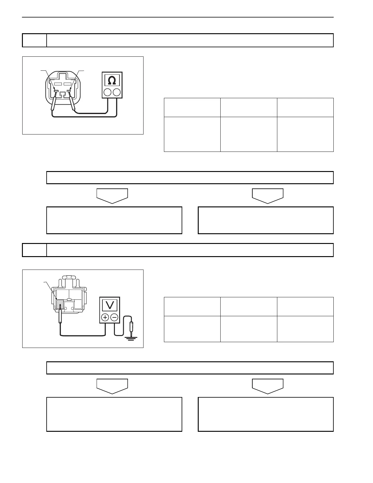
2. Disconnect the brake switch connector.
3. Use the electrical tester to measure the resistance between the
terminals of the brake switch.
1. Set the starter key to the "ON" position.
2. Use the electrical circuit to measure the voltage between the NC+
terminal in the brake switch vehicle side connector and ground.
3
Inspect the brake switch unit
Measurement
conditions
Tester
connections
Standard values
Starter key: LOCK
Brake switch
NC+ – NC-
• Depress brake
pedal:
• Release brake
pedal: 2 max.
Do the measurements meet the standard value?
Go to step 4. Replace the brake switch.
Perform "After-inspection work" of INFOR-
MATION section.
4
Check the brake switch power supply
Measurement
conditions
Tester
connections
Standard values
Starter key: ON
Brake switch vehi-
cle side connector
NC+ – Ground
More than 10 V
Do the measurements meet the standard value?
Go to step 5. Repair or replace the brake switch power
supply circuit (fuse, wire harness).
Perform "After-inspection work" of INFOR-
MATION section.
 Loading...