ENGINE (J05E)/TROUBLESHOOTING2–700
1. Set the starter key to the "LOCK" position.
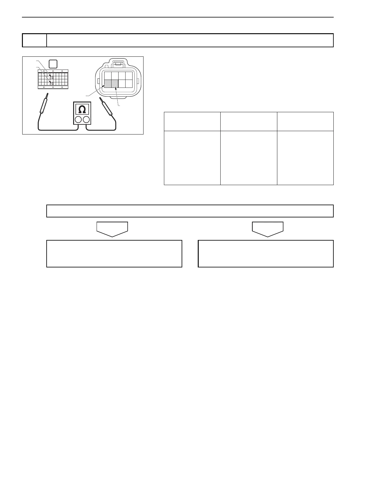
2. Connect the signal check harness to the engine ECU vehicle side
harness. (Do not connect the harness to the ECU.)
3. Use the electrical tester to measure the resistance between the
GCU vehicle side connector terminals and engine ECU (signal
check harness) terminals.
4
Inspect the harness of the GCU
V15
Measurement
conditions
Tester
connections
Standard values
Starter key: LOCK
GCU vehicle side
connector termi-
nals – engine ECU
(signal check har-
ness) terminals
DI – Dl (V35)
Sl – ST (V15)
1 or less
Do the measurements meet the standard value?
Go to step 5. Repair or replace the harness.
Perform "After-inspection work" of INFOR-
MATION section.
 Loading...