ENGINE (J05E)/TROUBLESHOOTING2–670
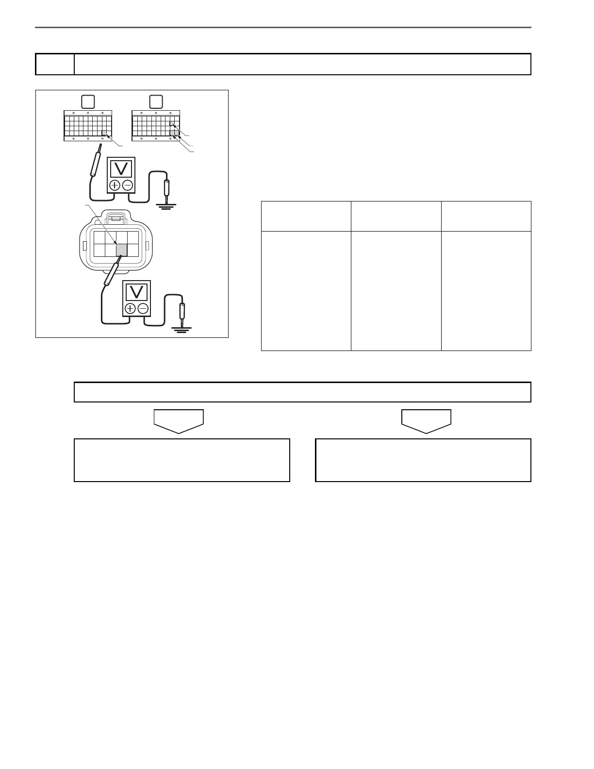
1. Set the starter key to the "ON" position.
2. Use the electrical tester to measure the voltage between each ter-
minal in the engine ECU (signal check harness) and ground.
3. Measure the voltage between the GND terminal in the glow control
unit vehicle side connector and ground.
4. Check the difference in potential between the engine ECU and the
ground circuit of the glow control unit.
5
Inspect the ground circuit voltage
Measurement
conditions
Tester
connections
Standard values
Starter key: ON
Engine ECU (sig-
nal check har-
ness)
E01(V39) – Ground
E02(V59) – Ground
E03(V79) – Ground
E04(V80) – Ground
GCU vehicle side
connector
GND – Ground
Potential differ-
ence:
within 400 mV
Do the measurements meet the standard value?
Replace the GCU.
Perform "After-inspection work" of INFOR-
MATION section.
Inspect the ground circuit.
Perform "After-inspection work" of INFOR-
MATION section.
 Loading...