ENGINE (J05E)/TROUBLESHOOTING2–202
1. Check the installation of the air flow sensor.
2. Make sure there is no dirt, damage or clogging in the sensing unit
of the air flow sensor.
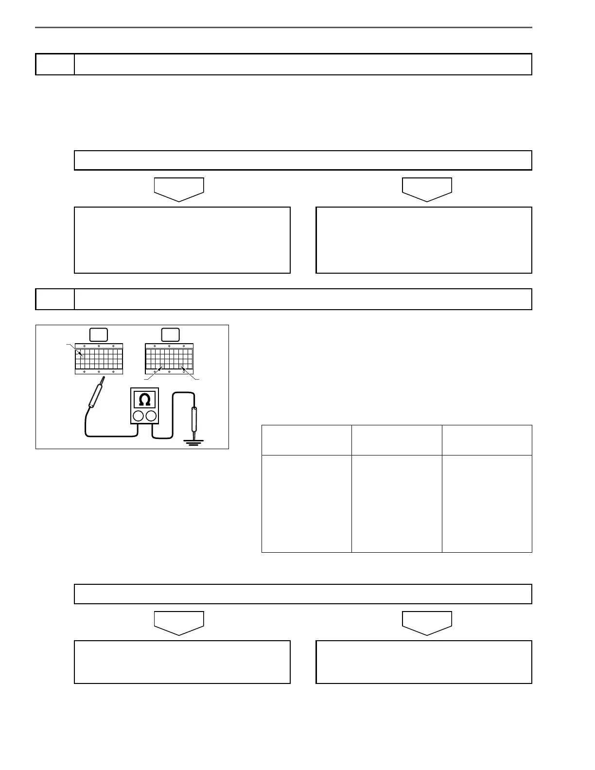
1. Set the starter key to the "LOCK" position.
2. Disconnect the air flow sensor connector.
3. Connect the signal check harness to the engine ECU vehicle side
harness. (Do not connect harness to the ECU.)
4. Use the electrical tester to measure the resistance between the
engine ECU (signal check harness) terminals and ground.
3
Inspect the air flow sensor
Was any failure found?
Clean the sensing unit and install it properly.
If dirt, clogging or damage was found,
replace the air flow sensor.
Perform "After-inspection work" of INFOR-
MATION section.
Go to step 4.
4
Inspect for short-circuits in wire harness of air flow sensor
Measurement
conditions
Tester
connections
Standard values
Starter key: LOCK
Engine ECU (sig-
nal check har-
ness)
VAF (E12) –
Ground
VG (E74) – Ground
EVG (E78) –
Ground
Do the measurements meet the standard value?
Go to step 5. Repair or replace the harness.
Perform "After-inspection work" of INFOR-
MATION section.
 Loading...