ENGINE (J05E)/TROUBLESHOOTING 2–459
1. Connect the engine speed sub sensor (camshaft position sensor)
connector.
2. Start the engine.
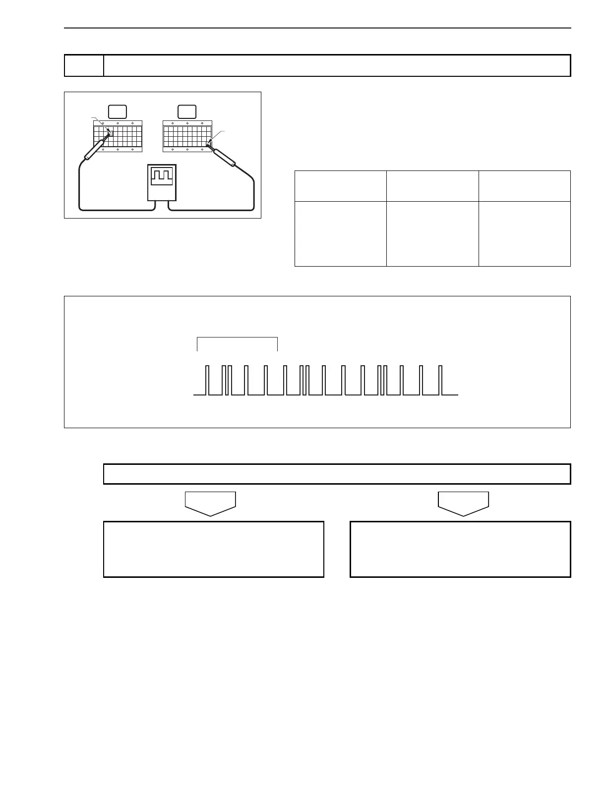
3. Use the oscilloscope to measure the signal voltage between the
terminals in the engine ECU (signal check harness).
6
Inspect the engine speed sub sensor (camshaft position sensor) signal
Measurement
conditions
Tester
connections
Standard values
With engine idling
Engine ECU (sig-
nal check har-
ness)
G+ (E73) – E04
(V80)
Pulse 5
Do the measurements meet the standard value?
Go to step 7. Replace the engine speed sub sensor (cam-
shaft position sensor).
Perform "After-inspection work" of INFOR-
MATION section.
 Loading...