ENGINE (J05E)/TROUBLESHOOTING 2–611
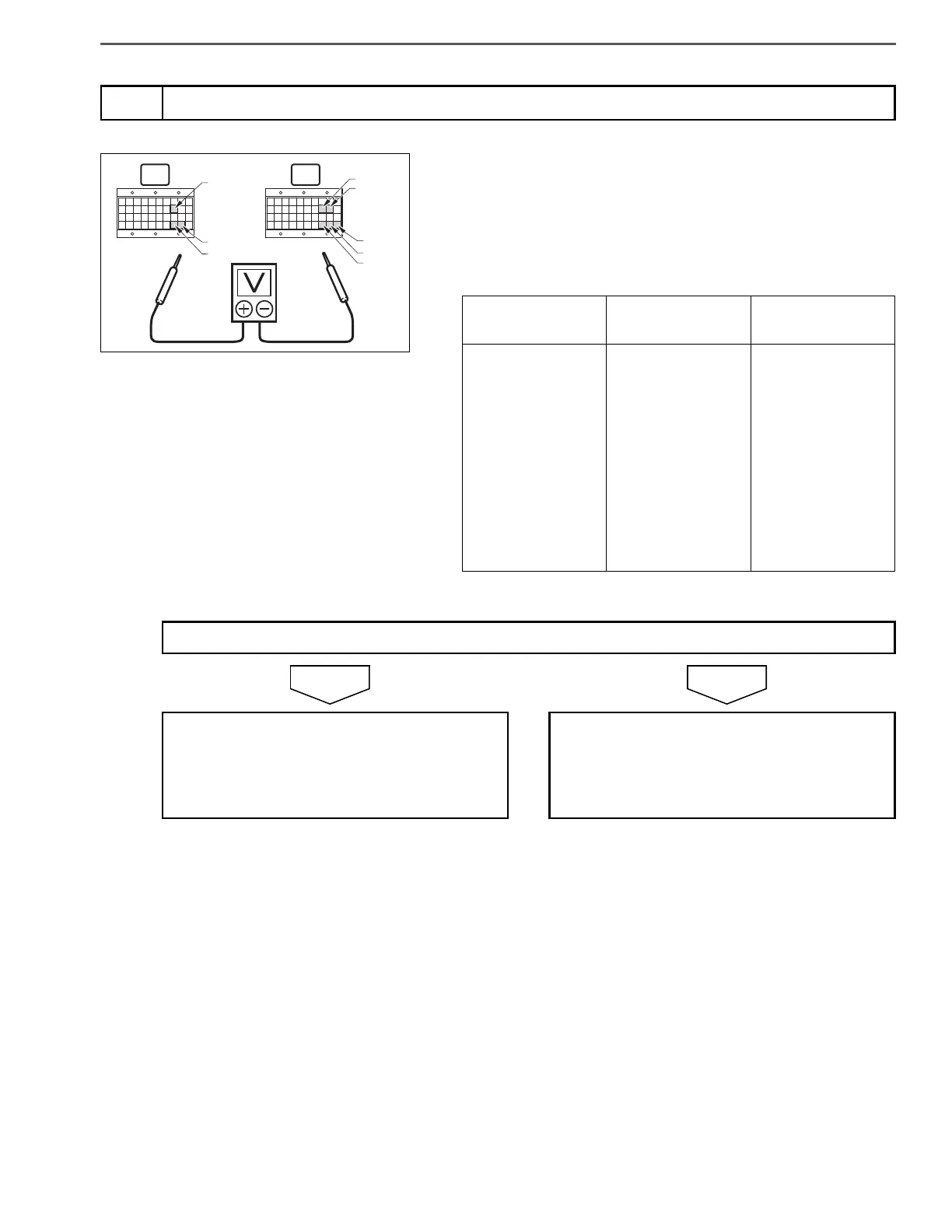
1. Set the starter key to the "LOCK" position.
2. Connect the signal check harness to the engine ECU.
3. Start the engine.
4. Use the electrical tester to measure the voltage between the termi-
nals of the engine ECU (signal check harness).
4
Inspect the engine ECU power supply
A B
V59
V58
V38
V39
V18
V79
V78
V80
Measurement
conditions
Tester
connections
Standard values
Engine idling
Engine ECU (sig-
nal check har-
ness)
(+) – (-)
+B (V18) – E01
(V39)
+B1 (V38) – E02
(V59)
+B2 (V58) – E03
(V79)
+BM (V78) – E04
(V80)
10 – 16 V
Do the measurements meet the standard value?
Go to step 5. Check the engine ECU wire harness (power
supply circuit).
Repair or replace parts as needed.
Perform "After-inspection work" of INFOR-
MATION section.
 Loading...