EasyManuals Logo

Hino Motors HINO 195 series User Manual

Hino Motors HINO 195 series
860 pages
To Next Page IconTo Next Page
To Previous Page IconTo Previous Page
Page #248 background imageLoading...
Page #248 background image
ENGINE (J05E)/TROUBLESHOOTING2–212
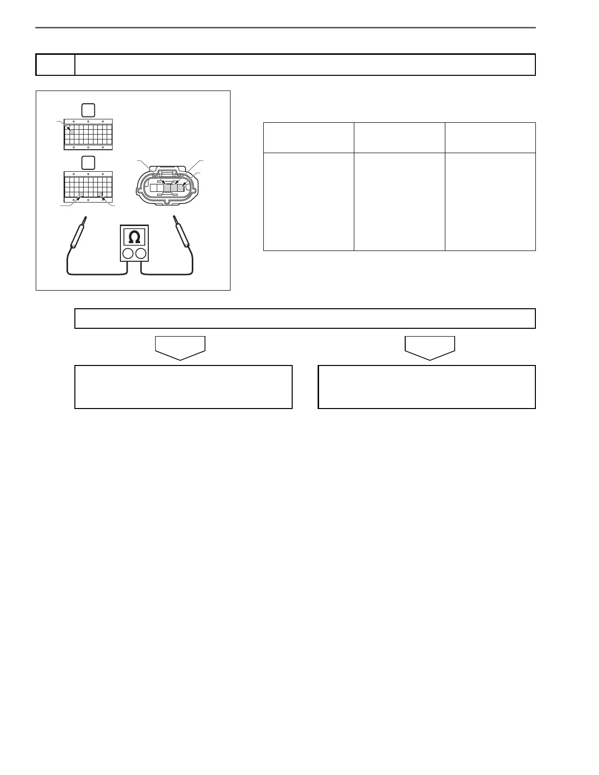
1. Use the electrical tester to measure the resistance between the
terminals of the engine ECU (signal check harness) and air flow
sensor vehicle side connector.
NOYES
5
Inspect disconnection of the air flow sensor harness
C
D
E12
E78E74
FC
E2G+B
SHTS021270300193
Measurement
conditions
Tester
connections
Standard values
Starter key: LOCK
Engine ECU (sig-
nal check har-
ness) Air flow
sensor vehicle
side connector
VG (E74) FC
EVG (E78) E2G
VAF (E12) +B
1 or less
Do the measurements meet the standard value?
Go to step 6. Repair or replace the harness.
Perform "After-inspection work" of INFOR-
MATION section.

Table of Contents

Questions and Answers:

Question and Answer IconNeed help?

Do you have a question about the Hino Motors HINO 195 series and is the answer not in the manual?

Hino Motors HINO 195 series Specifications

General IconGeneral
BrandHino Motors
ModelHINO 195 series
CategoryTrucks
LanguageEnglish

Related product manuals