EasyManuals Logo

Hino Motors HINO 195 series User Manual

Hino Motors HINO 195 series
860 pages
To Next Page IconTo Next Page
To Previous Page IconTo Previous Page
Page #249 background imageLoading...
Page #249 background image
ENGINE (J05E)/TROUBLESHOOTING 2–213
1. Connect the signal check harness to the engine ECU.
2. Set the starter key to the "ON" position.
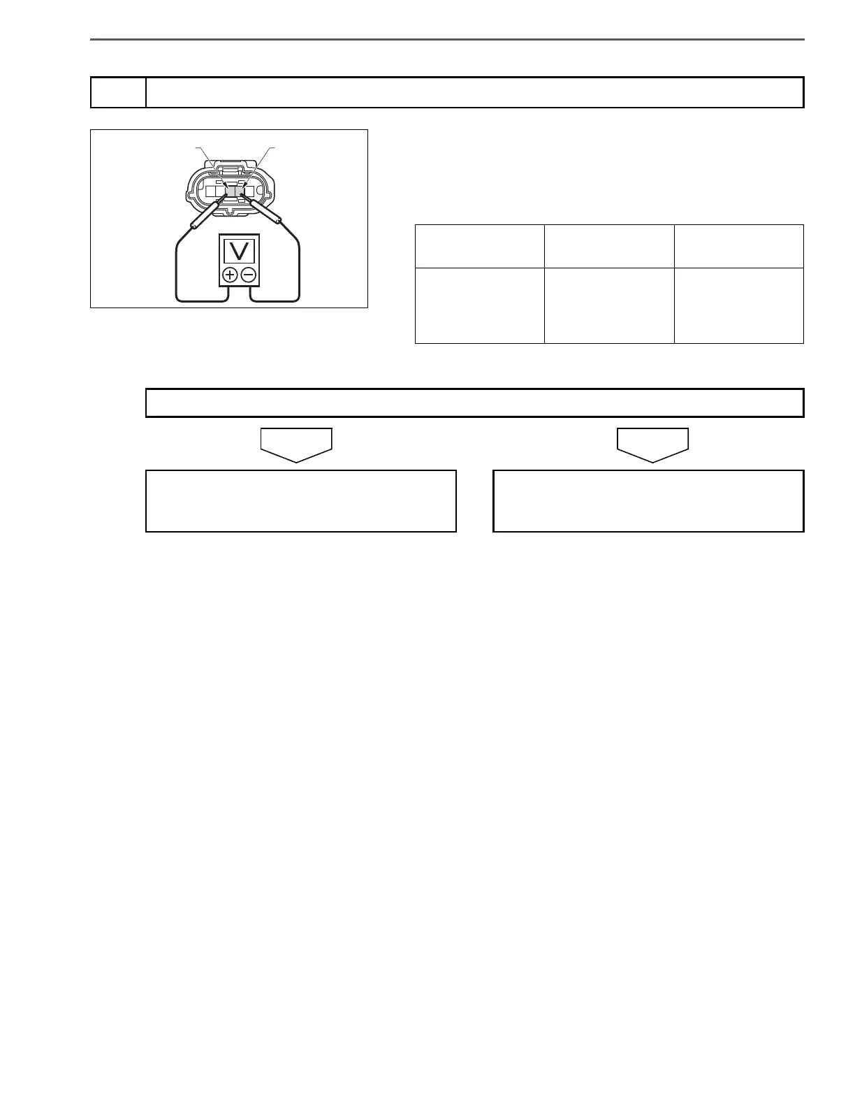
3. Use the electrical tester to measure the voltage between the termi-
nals of the air flow sensor vehicle side connector.
NOYES
6
Inspect the air flow sensor power supply
SHTS021270300194
Measurement
conditions
Tester
connections
Standard values
Starter key: ON
Air flow sensor
vehicle side con-
nector
+B E2G
10 16 V
Do the measurements meet the standard value?
Go to step 7. Replace the engine ECU.
Perform "After-inspection work" of INFOR-
MATION section.

Table of Contents

Questions and Answers:

Question and Answer IconNeed help?

Do you have a question about the Hino Motors HINO 195 series and is the answer not in the manual?

Hino Motors HINO 195 series Specifications

General IconGeneral
BrandHino Motors
ModelHINO 195 series
CategoryTrucks
LanguageEnglish

Related product manuals