ENGINE (J05E)/TROUBLESHOOTING2–688
INSPECTION PROCEDURE: P0671 and P0672
1. Check for fusing and improper fit.
1. Set the starter key to the "LOCK" position.
2. Disconnect the GCU connector.
3. Use the electrical tester to measure the voltage between the termi-
nals of the GCU vehicle side connector.
1
Inspect the fusible link (GLOW)
Was any failure found?
Connect the fusible link correctly or replace
it.
Perform "After-inspection work" of INFOR-
MATION section.
Go to step 2.
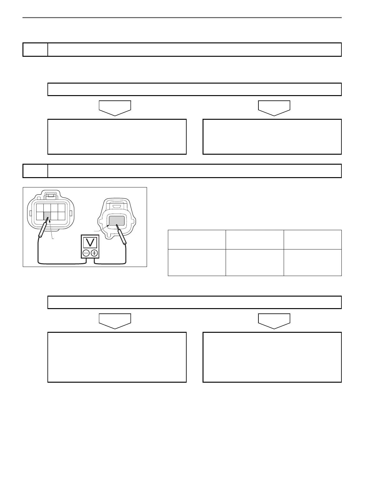
2
Inspect the power supply wire harness of the glow control unit (GCU)
Measurement
conditions
Tester
connections
Standard values
Starter key: LOCK
GCU vehicle side
connector
+B – GND
10 – 16 V
Do the measurements meet the standard value?
Go to step 3. Repair or replace the wire harness in the
glow control unit power supply circuit
(between the fusible link and the control
unit).
Perform "After-inspection work" of INFOR-
MATION section.
 Loading...