EasyManua.ls Logo

HP ProLiant DL380 - G2 Server User Manual

HP ProLiant DL380 - G2 Server
126 pages
To Next Page IconTo Next Page
Page #1 background imageLoading...
Page #1 background image
COMPAQ CONFIDENTIAL Codename: Magna Part Number: 203840-003 Last Saved On: 1/28/02 12:48 PM
ProLiant DL380 Generation 2 Server
Maintenance and Service Guide
Part Number 203840-003
Spare Part Number 228520-001
January 2002 (Third Edition)

Table of Contents

Question and Answer IconNeed help?

Do you have a question about the HP ProLiant DL380 - G2 Server and is the answer not in the manual?

HP ProLiant DL380 - G2 Server Specifications

General IconGeneral
Form Factor2U Rackmount
CPUIntel Pentium III or Xeon
StorageUp to 6 hot-plug SCSI drives
Network ControllerIntegrated 10/100TX Ethernet
Power SupplyDual redundant hot-plug
Expansion Slots6 PCI (4x 64-bit, 2x 32-bit)

Summary

About This Guide

Guide Introduction and Safety Information

Introduces the manual, covers safety, and technician notes.

Additional Help and Text Conventions

Provides resources for assistance and explains document text conventions.

Chapter 1 Illustrated Parts Catalog

Mechanical Components Identification

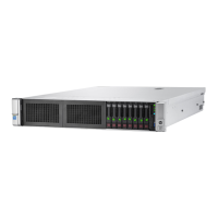
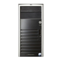
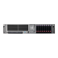
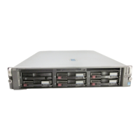
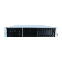
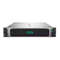
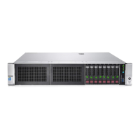
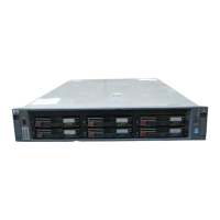
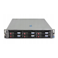
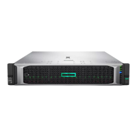
Lists and illustrates external mechanical parts with their part numbers.

System Components Identification

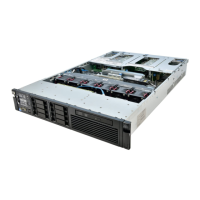
Lists and illustrates internal system components and boards with part numbers.

Chapter 2 Removal and Replacement Procedures

Safety and Preparation for Service

Covers safety warnings, symbols, and necessary preparation steps before servicing.

Hot-Plug Component Procedures

Step-by-step instructions for hot-plug component removal and replacement.

Non-Hot-Plug Component Procedures

Step-by-step instructions for non-hot-plug component removal and replacement.

Chapter 3 Diagnostic Tools

Server Diagnostic Software and Utilities

Lists and describes tools for diagnosing, testing, and managing the server.

Chapter 4 Connectors, LED Indicators, Switches, and Jumpers

Rear Panel and System Board Connectors

Identifies and describes external and internal connectors on the server.

Component Status Indicators (LEDs)

Explains the meaning and status of various LEDs on the server.

System Configuration Switches

Details the function and location of system switches on the motherboard.

Bootblock Flash Jumper

Describes the jumper for configuring system ROM bootblock flashing.

Chapter 5 Specifications

System Unit and Core Component Specifications

Provides physical, environmental, and electrical specs for the server and its main parts.

Drive and Memory Specifications

Details specifications for DIMMs, diskette drives, CD-ROM drives, and SCSI hard drives.

Related product manuals