95
• CIST IRPC—Internal root path cost (IRPC) from the originating bridge to the root of the MST
region.
• CIST bridge ID—ID of the bridge that sends the MSTP BPDU.
• CIST remaining ID—Remaining hop count. This field limits the scale of the MST region. The
regional root sends a BPDU with the remaining hop count set to the maximum value. Each
device that receives the BPDU decrements the hop count by one. When the hop count reaches
zero, the BPDU is discarded. Devices beyond the maximum hops of the MST region cannot
participate in spanning tree calculation. The default remaining hop count is 20.
• MSTI configuration messages—Contains MSTI configuration messages. Each MSTI
configuration message is 16 bytes. This field can contain 0 to 64 MSTI configuration messages.
The number of the MSTI configuration messages is determined by the number of MSTIs in the
MST region.
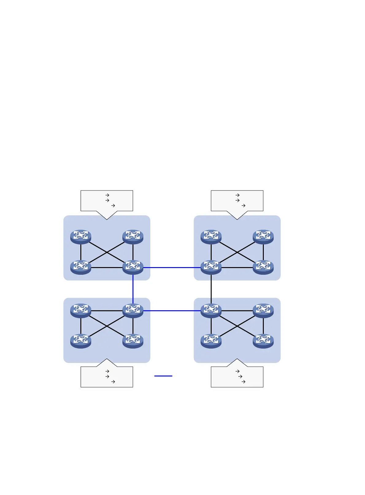
MSTP basic concepts
Figure 30 shows a switched network that contains four MST regions, each MST region containing
four MSTP devices. Figure 31 sh
ows the networking topology of MST region 3.
Figure 30 Basic concepts in MSTP
MST region 1
MST region 2 MST region 3
MST region 4
VLAN 1 MSTI 1
VLAN 2
MSTI 2
Other VLANs
MSTI 0
VLAN 1 MSTI 1
VLAN 2
MSTI 2
Other VLANs
MSTI 0
VLAN 1 MSTI 1
VLAN 2
MSTI 2
Other VLANs
MSTI 0
VLAN 1 MSTI 1
VLAN 2&3
MSTI 2
Other VLANs
MSTI 0
CST

 Loading...


