283
[PE1-Ten-GigabitEthernet1/0/2] port trunk permit vlan all
[PE1-Ten-GigabitEthernet1/0/2] quit
2. Configure PE 2 in the same way PE 1 is configured. (Details not shown.)
Verifying the configuration
# Verify that the root bridge of Customer A's network is CE 1.
<CE2> display stp root
MST ID Root Bridge ID ExtPathCost IntPathCost Root Port
0 32768.00e0-fc02-5800 0 0
# Verify that the root bridge of the service provider network is not CE 1.
[PE1] display stp root
MST ID Root Bridge ID ExtPathCost IntPathCost Root Port
0 32768.0cda-41c5-ba50 0 0
Configuring L2PT for LACP
Network requirements
As shown in Figure 93, the MAC addresses of CE 1 and CE 2 are 0001-0000-0000 and
0004-0000-0000, respectively.
Perform the following tasks:
• Configure Ethernet link aggregation on CE 1 and CE 2.
• Configure Ten-GigabitEthernet 1/0/1 and Ten-GigabitEthernet 1/0/2 on CE 1 to form aggregate
links with Ten-GigabitEthernet 1/0/1 and Ten-GigabitEthernet 1/0/2 on CE 2, respectively.
• Enable L2PT for LACP to enable CE 1 and CE 2 to implement Ethernet link aggregation across
the service provider network.
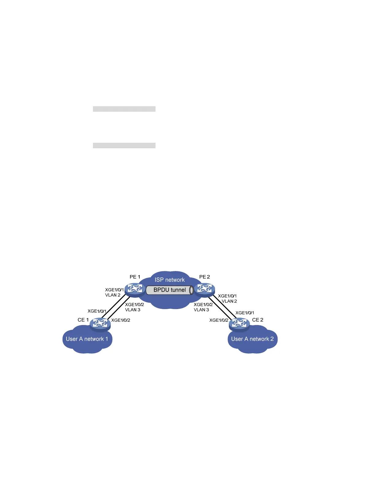
Figure 93 Network diagram
Requirements analysis
To meet the network requirements, perform the following tasks:
• For Ethernet link aggregation to operate correctly, configure VLANs on the PEs to ensure
point-to-point transmission between CE 1 and CE 2 in an aggregation group.
{ Set the PVIDs to VLAN 2 and VLAN 3 for Ten-GigabitEthernet 1/0/1 and
Ten-GigabitEthernet 1/0/2 on PE 1, respectively.
{ Configure PE 2 in the same way PE 1 is configured.
{ Configure ports that connect to the CEs as trunk ports.
• To retain the VLAN tag of the customer network, enable QinQ on Ten-GigabitEthernet 1/0/1 and
Ten-GigabitEthernet 1/0/2 on both PE 1 and PE 2.

 Loading...


