76
XGE1/0/4 S 32768 2
The output shows that:
• Link aggregation groups 1 and 2 are both load-shared Layer 3 static aggregation groups.
• Each aggregation group contains two Selected ports.
# Display all the group-specific load sharing modes on Device A.
[DeviceA] display link-aggregation load-sharing mode interface
Route-Aggregation1 Load-Sharing Mode:
source-ip address
Route-Aggregation2 Load-Sharing Mode:
destination-ip address
The output shows that:
• Link aggregation group 1 load shares packets based on source IP addresses.
• Link aggregation group 2 load shares packets based on destination IP addresses.
Layer 3 edge aggregate interface configuration example
Network requirements
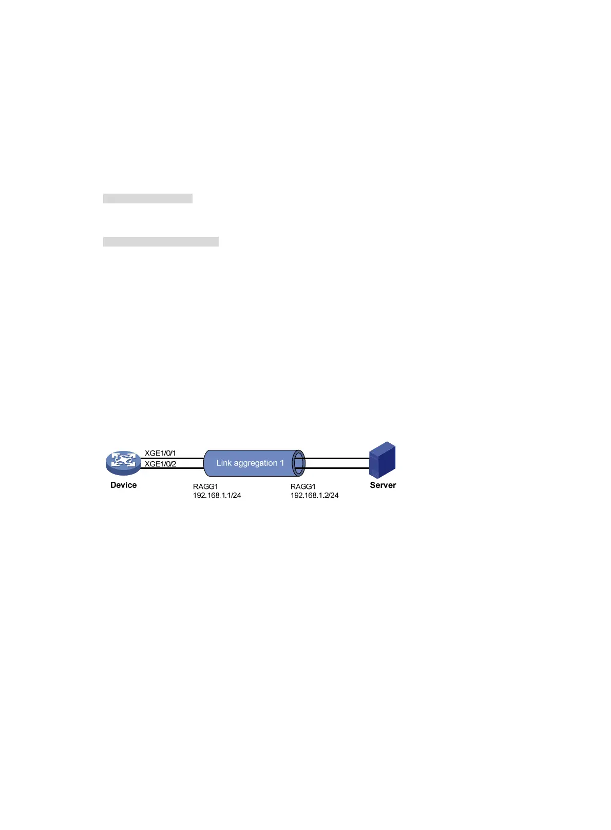
As shown in Figure 20, a Layer 3 dynamic aggregation group is configured on the device. The server
is not configured with dynamic link aggregation.
Configure an edge aggregate interface so that both Ten-GigabitEthernet 1/0/1 and
Ten-GigabitEthernet 1/0/2 can forward traffic to improve link reliability.
Figure 20 Network diagram
Configuration procedure
# Create Layer 3 aggregate interface Route-Aggregation 1, and set the link aggregation mode to
dynamic.
<Device> system-view
[Device] interface route-aggregation 1
[Device-Route-Aggregation1] link-aggregation mode dynamic
# Configure an IP address and subnet mask for Layer 3 aggregate interface Route-Aggregation 1.
[Device-Route-Aggregation1] ip address 192.168.1.1 24
# Configure Layer 3 aggregate interface Route-Aggregation 1 as an edge aggregate interface.
[Device-Route-Aggregation1] lacp edge-port
[Device-Route-Aggregation1] quit
# Assign Layer 3 Ethernet interfaces Ten-GigabitEthernet 1/0/1 and Ten-GigabitEthernet 1/0/2 to
aggregation group 1.
[Device] interface ten-gigabitethernet 1/0/1
[Device-Ten-GigabitEthernet1/0/1] port link-aggregation group 1
[Device-Ten-GigabitEthernet1/0/1] quit

 Loading...


