66
--------------------------------------------------------------------------------
XGE1/0/1 S 32768 1
XGE1/0/2 S 32768 1
XGE1/0/3 S 32768 1
The output shows that link aggregation group 1 is a Layer 2 static aggregation group that contains
three Selected ports.
Layer 2 dynamic aggregation configuration example
Network requirements
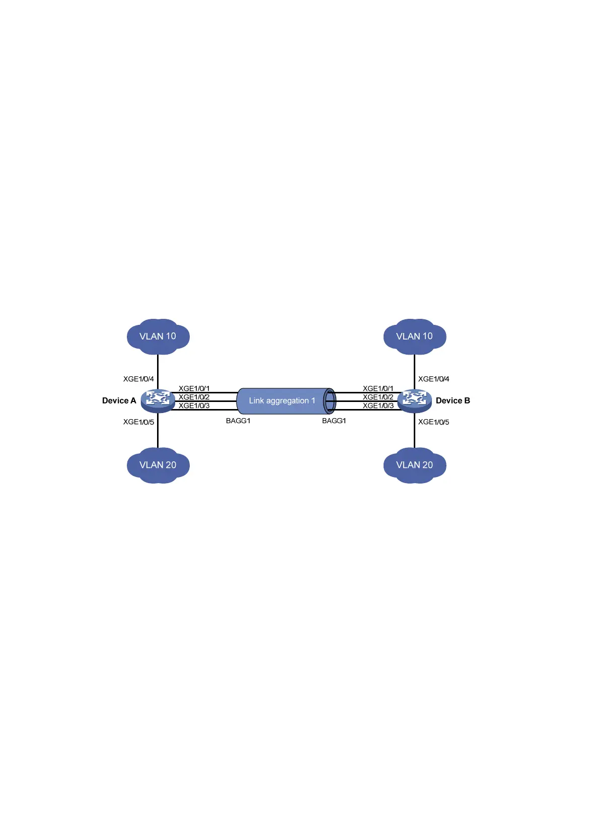
On the network shown in Figure 14, perform the following tasks:
• Configure a Layer 2 dynamic aggregation group on both Device A and Device B.
• Enable VLAN 10 at one end of the aggregate link to communicate with VLAN 10 at the other
end.
• Enable VLAN 20 at one end of the aggregate link to communicate with VLAN 20 at the other
end.
Figure 14 Network diagram
Configuration procedure
1. Configure Device A:
# Create VLAN 10, and assign the port Ten-GigabitEthernet 1/0/4 to VLAN 10.
<DeviceA> system-view
[DeviceA] vlan 10
[DeviceA-vlan10] port ten-gigabitethernet 1/0/4
[DeviceA-vlan10] quit
# Create VLAN 20, and assign the port Ten-GigabitEthernet 1/0/5 to VLAN 20.
[DeviceA] vlan 20
[DeviceA-vlan20] port ten-gigabitethernet 1/0/5
[DeviceA-vlan20] quit
# Create Layer 2 aggregate interface Bridge-Aggregation 1, and set the link aggregation mode
to dynamic.
[DeviceA] interface bridge-aggregation 1
[DeviceA-Bridge-Aggregation1] link-aggregation mode dynamic
[DeviceA-Bridge-Aggregation1] quit

 Loading...


