68
Layer 2 aggregation load sharing configuration example
Network requirements
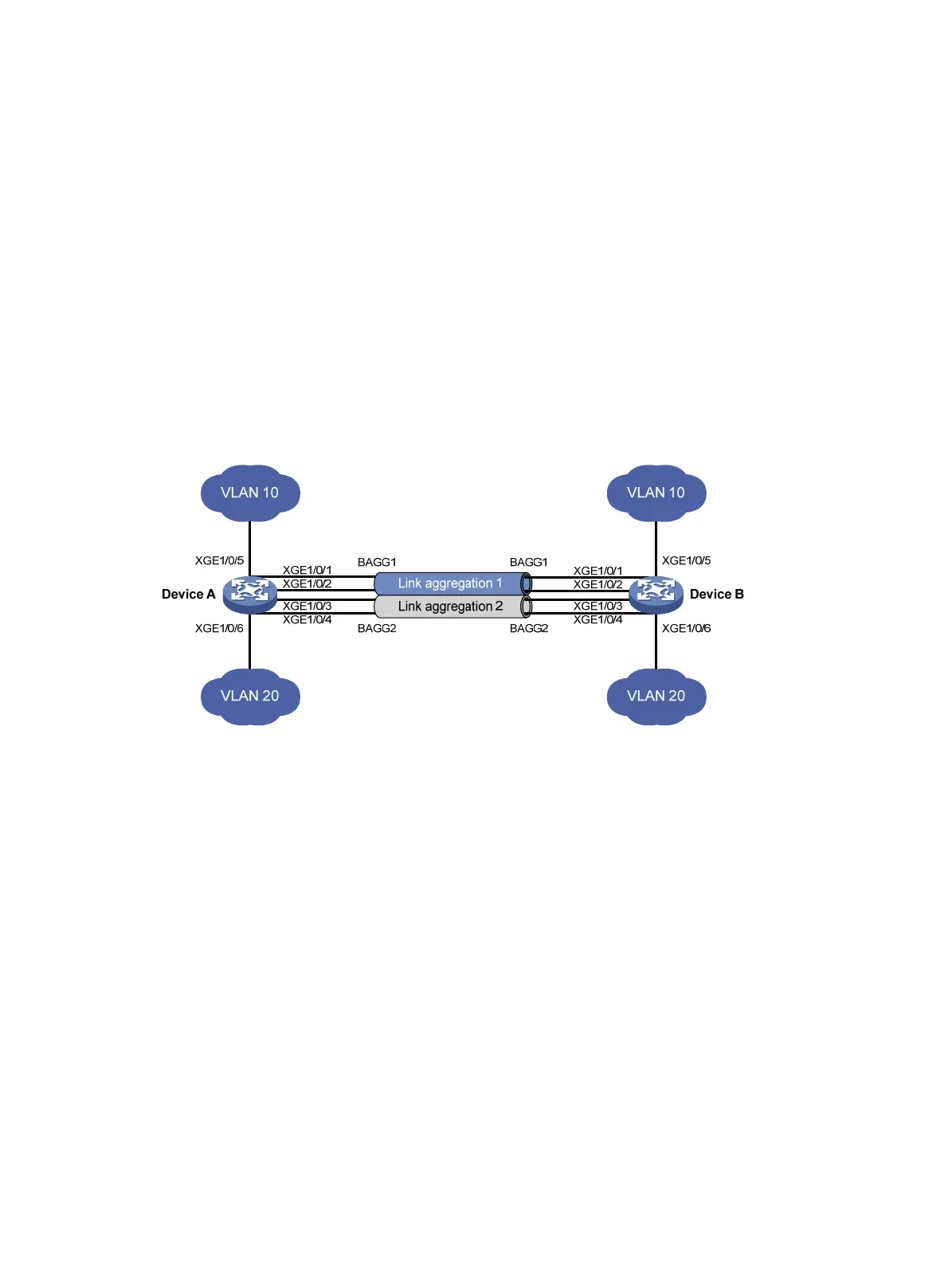
On the network shown in Figure 15, perform the following tasks:
• Configure Layer 2 static aggregation groups 1 and 2 on Device A and Device B, respectively.
• Enable VLAN 10 at one end of the aggregate link to communicate with VLAN 10 at the other
end.
• Enable VLAN 20 at one end of the aggregate link to communicate with VLAN 20 at the other
end.
• Configure link aggregation groups 1 and 2 to load share traffic across aggregation group
member ports.
{ Configure link aggregation group 1 to load share packets based on source MAC addresses.
{ Configure link aggregation group 2 to load share packets based on destination MAC
addresses.
Figure 15 Network diagram
Configuration procedure
1. Configure Device A:
# Create VLAN 10, and assign the port Ten-GigabitEthernet 1/0/5 to VLAN 10.
<DeviceA> system-view
[DeviceA] vlan 10
[DeviceA-vlan10] port ten-gigabitethernet 1/0/5
[DeviceA-vlan10] quit
# Create VLAN 20, and assign the port Ten-GigabitEthernet 1/0/6 to VLAN 20.
[DeviceA] vlan 20
[DeviceA-vlan20] port ten-gigabitethernet 1/0/6
[DeviceA-vlan20] quit
# Create Layer 2 aggregate interface Bridge-Aggregation 1.
[DeviceA] interface bridge-aggregation 1
# Configure Layer 2 aggregation group 1 to load share packets based on source MAC
addresses.
[DeviceA-Bridge-Aggregation1] link-aggregation load-sharing mode source-mac
[DeviceA-Bridge-Aggregation1] quit
# Assign ports Ten-GigabitEthernet 1/0/1 and Ten-GigabitEthernet 1/0/2 to link aggregation
group 1.

 Loading...


