4 Installation and Commissioning
Copyright © Huawei Technologies Co., Ltd.
Procedure
Step 1 Remove the rear cover from the T/H sensor to expose the interior panel.
Step 2 Prepare RJ45 connectors on both ends of a network cable, as shown in Figure 4-13.
Step 3 Route the network cable through the hole on the rear cover middle, then plug one RJ45
connector to an RS485 port with 12 V power supply in the ECC500 and the other one to the
RS485 port in the T/H sensor.
----End
4.3.5.4 Connecting the UPS2000-G-B Monitoring Cable
Context
When connecting a UPS2000-G-B to the ECC500, perform the following steps to
prepare a special monitoring cable.
The cable connection method described in the section applies to cable connections from
the ports of the RS485 expansion card in the ECC500 to devices.
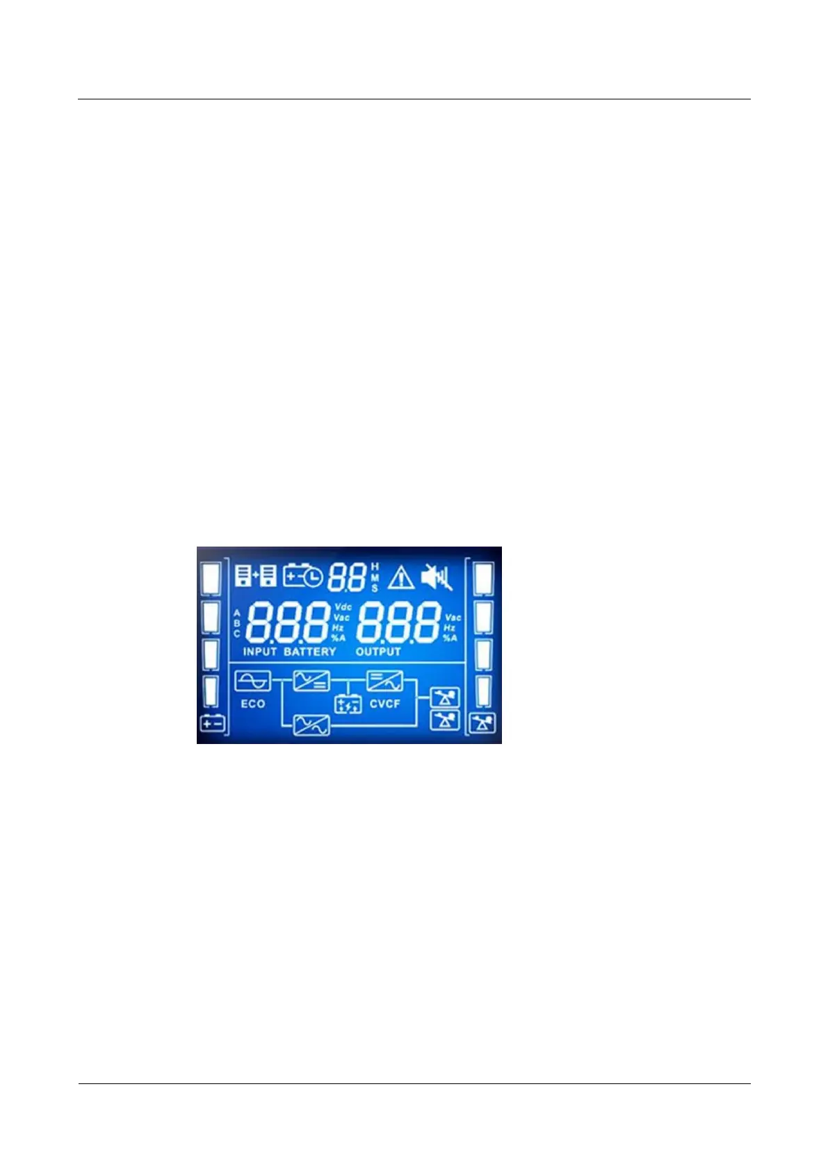
UPS2000-G-B V200R001 is used and equipped with an LCD screen, as shown in Figure
4-15.
Figure 4-15 LCD screen display
Procedure
Step 1 Prepare an RJ45 connector on one end of a network cable, as shown in Figure 4-13.
Step 2 Prepare a special RJ45 connector (exchange No. 4 and 5 wires) on the other end of the cable,
as shown in Figure 4-16.