4 Installation and Commissioning
Copyright © Huawei Technologies Co., Ltd.
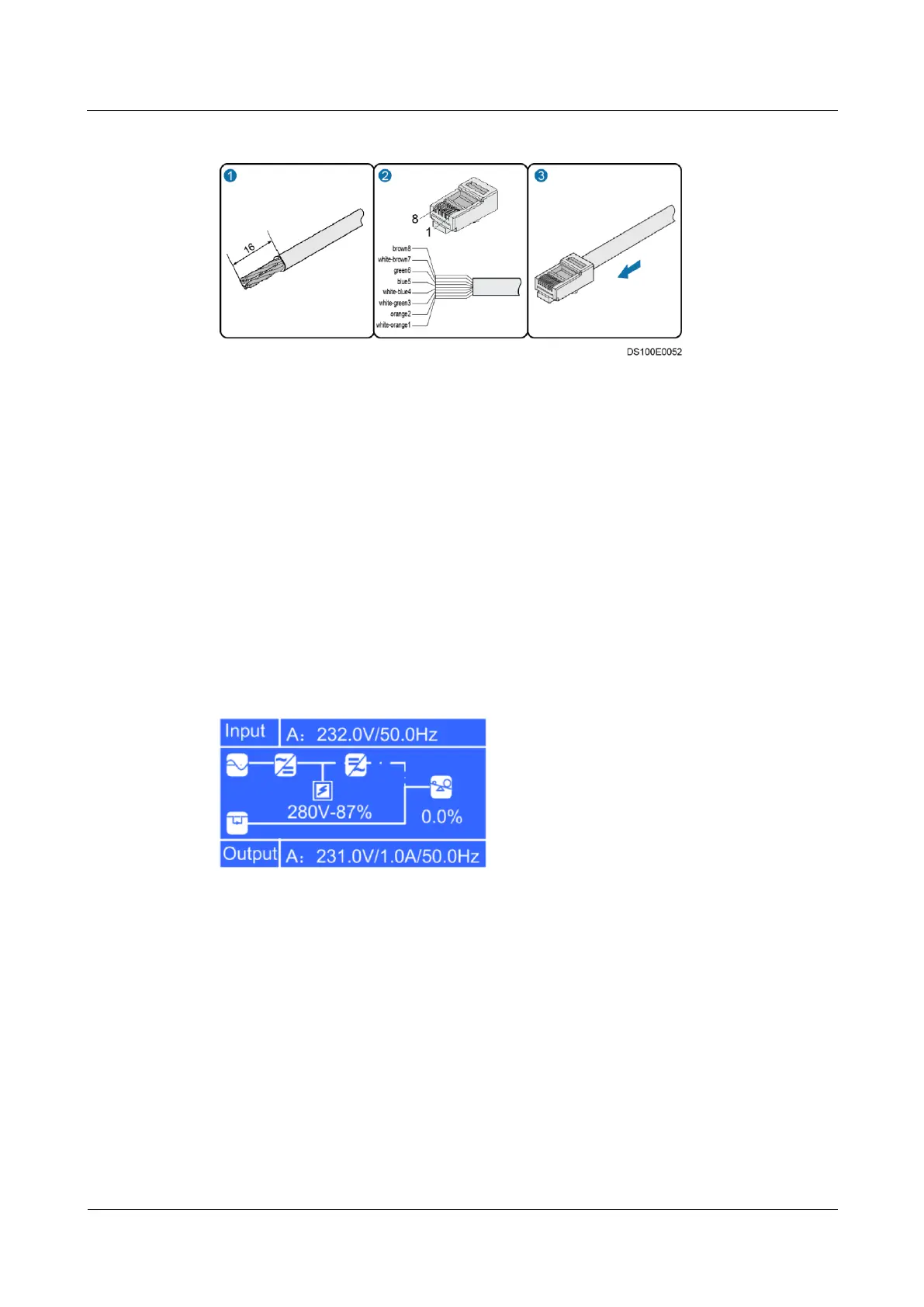
Figure 4-16 Preparing a special RJ45 connector (unit: mm)
Step 3 Plug the common RJ45 connector to an RS485 port in the ECC500 and the special one to the
RS485 port in the UPS2000-G-B.
----End
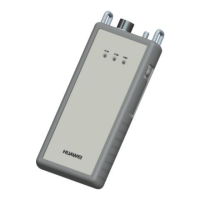
4.3.5.5 Connecting the UPS2000-G-A Monitoring Cable
Context
The cable connection method described in the section applies to cable connections from
the ports of the RS485 expansion card in the ECC500 to devices.
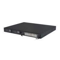
UPS2000-G-A V100R001 is used and equipped with an LCD screen, as shown in Figure
4-17.
Figure 4-17 LCD screen display
Procedure
Step 1 Prepare RJ45 connectors on both ends of a network cable, as shown in Figure 4-13.
Step 2 Plug one RJ45 connector to an RS485 port in the ECC500 and the other one to the RS485 port
in the UPS2000-G-A.
----End