4 Installation and Commissioning
Copyright © Huawei Technologies Co., Ltd.
Toggles 1 to 8 of DIP switch S2 specify the device address in binary mode. ON indicates 0,
and OFF indicates 1. Table 4-4 shows an example of the switch settings.
Table 4-4 Mapping between device addresses and Modbus card DIP switch settings
----End
4.4.4 Setting the UPS2000-G-B Device Address
Context
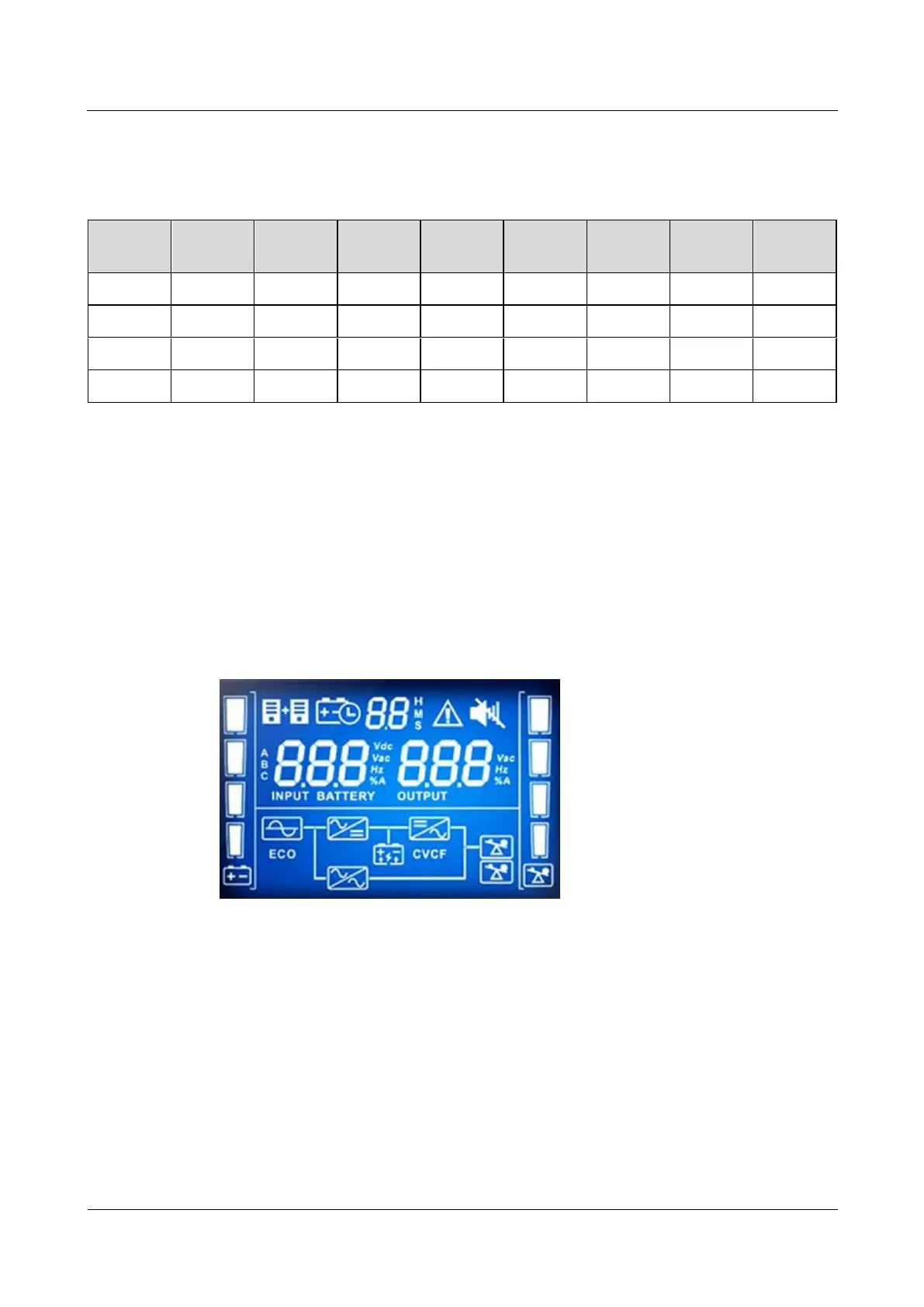
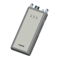
UPS2000-G-B V200R001 is used and equipped with an LCD screen, as shown in Figure
4-26.
Figure 4-26 LCD screen display
Procedure
Step 1 Operate the DIP switch S1 on the optional Modbus card to set the UPS2000-G-B device
address.
Toggles 1 to 8 of DIP switch S1 specify the device address in binary mode. ON indicates 1,
and OFF indicates 0. Table 4-5 shows an example of the switch settings.