The other end is a reserved G 1/2 inch connector with inner screw threads.
Connect the other end to a hose or rigid pipe based on site requirements.
Step 2 Connect the external water inlet pipe and route pipes inside the cabinet according
to the actual conditions.
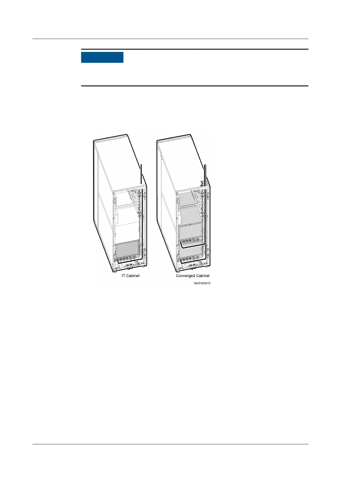
● Figure 4-63 shows the top routing of the water inlet pipe.
Figure 4-63 Top routing of the water inlet pipe
● Route the bottom water inlet pipe.
a. Break the rubber ring on the water pipe hole at the bottom of the
cabinet.
b. Figure 4-64 shows the bottom routing of the water inlet pipe.
FusionModule800 Smart Small Data Center
User Manual 4 Installation Guide
Issue 01 (2021-02-05) Copyright © Huawei Technologies Co., Ltd. 142