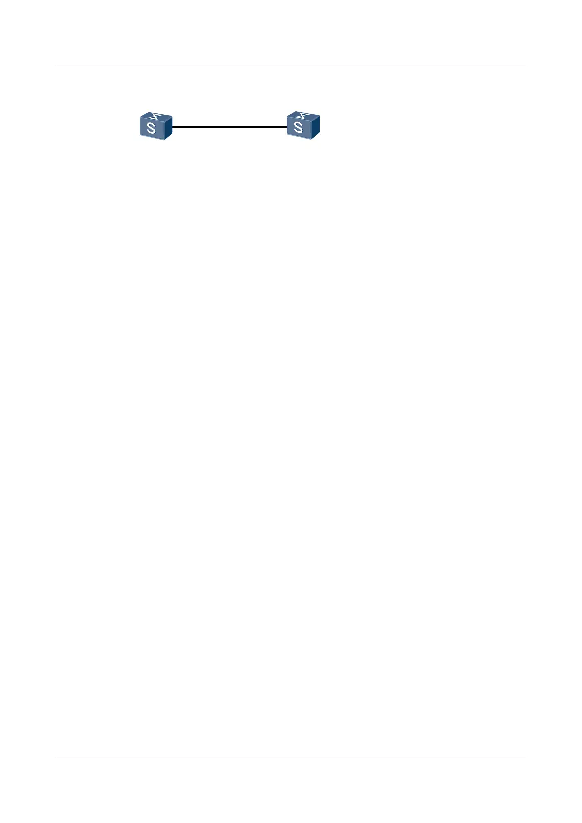
Figure 5-2 Networking diagram for configuring single-hop BFD on a VLANIF interface
XGE0/0/1
SwitchA SwitchB
VLANIF 13
10.1.1.6/24
VLANIF 13
10.1.1.5/24
XGE0/0/1
Configuration Roadmap
The configuration roadmap is as follows:
1. Create VLAN 13 on Switch A and Switch B.
2. Configure XGE 0/0/1 interfaces on Switch A and Switch B as hybrid interfaces.
3. Create VLANIF 13 on Switch A and Switch B and set their IP address.
4. Create a BFD session on Switch A to detect the link between Switch A and Switch B.
5. Create a BFD session on Switch B to detect the link between Switch B and Switch A.
Data Preparation
To complete the configuration, you need the following data:
l Numbers of VLANIF interfaces bound to BFD sessions
l IP addresses of VLANIF interfaces
l Local and remote discriminators of BFD sessions
Default values of minimum intervals for sending BFD control packets, minimum intervals for
receiving BFD control packets, and local detection multipliers
Procedure
Step 1 On Switch A and Switch B, create VLAN 13, configure XGE 0/0/1 interfaces as hybrid
interfaces, and add XGE 0/0/1 interfaces to VLAN 13.
# Configure Switch A.
<Quidway> system-view
[Quidway] sysname SwitchA
[SwitchA] vlan 13
[SwitchA-vlan13] quit
[SwitchA] interface xgigabitethernet 0/0/1
[SwitchA-XGigabitEthernet0/0/1] port hybrid pvid vlan 13
[SwitchA-XGigabitEthernet0/0/1] port hybrid untagged vlan 13
[SwitchA-XGigabitEthernet0/0/1] quit
# Configure SwitchB.
<Quidway> system-view
[Quidway] sysname SwitchB
[SwitchB] vlan 13
[SwitchB-vlan13] quit
[SwitchB] interface xgigabitethernet 0/0/1
[SwitchB-XGigabitEthernet0/0/1] port hybrid pvid vlan 13
[SwitchB-XGigabitEthernet0/0/1] port hybrid untagged vlan 13
[SwitchB-XGigabitEthernet0/0/1] quit
Quidway S6700 Series Ethernet Switches
Configuration Guide - Reliability 5 BFD Configuration
Issue 01 (2011-07-15) Huawei Proprietary and Confidential
Copyright © Huawei Technologies Co., Ltd.
206
 Loading...


