91
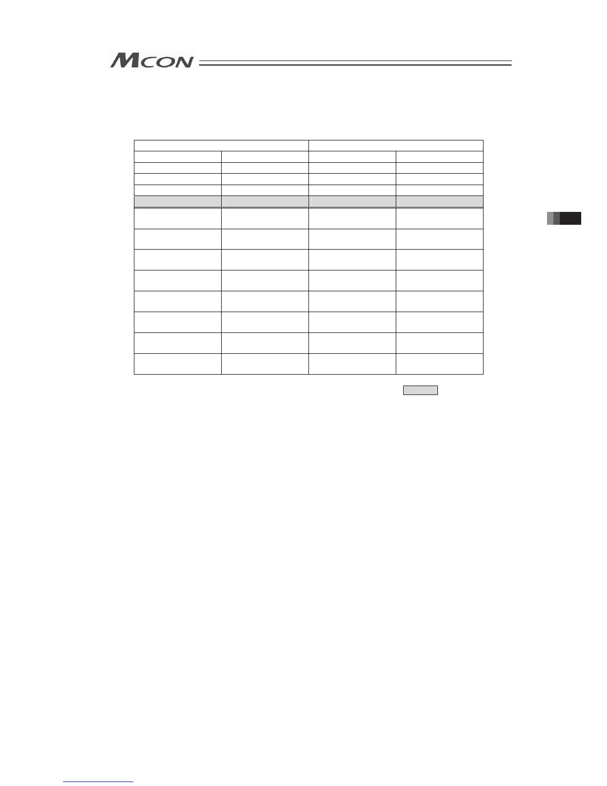
2) CC-Link and CC-Link IE Field
[Combination Example 1] When number of Simple Direct Mode/Positioner 1 Mode axes is
8 and number of Direct Indication Mode 0
CC-Link: (Extended Cyclic Setting/Number of Occupied
Stations: 4 times/2 stations)
PLC → MCON MCON → PLC
Address Description Address Description
RY 00 to 1F Gateway Control RX 00 to 1F Gateway Status
RY 20 to 6F Demand Command RX 20 to 6F Response Command
RY 70 to 7F Cannot be used. RX 70 to 7F Cannot be used.
RY 80 to BF Cannot be used. RX 80 to BF Cannot be used.
RWw 00 to 03
Axis No.0 Control
Information
RWr 00 to 03
Axis No.0 Status
Information
RWw 04 to 07
Axis No.1 Control
Information
RWr 04 to 07
Axis No.1 Status
Information
RWw 08 to 0B
Axis No.2 Control
Information
RWr 08 to 0B
Axis No.2 Status
Information
RWw 0C to 0F
Axis No.3 Control
Information
RWr 0C to 0F
Axis No.3 Status
Information
RWw 10 to 13
Axis No.4 Control
Information
RWr 10 to 13
Axis No.4 Status
Information
RWw 14 to 17
Axis No.5 Control
Information
RWr 14 to 17
Axis No.5 Status
Information
RWw 18 to 1B
Axis No.6 Control
Information
RWr 18 to 1B
Axis No.6 Status
Information
RWw 1C to 1F
Axis No.7 Control
Information
RWr 1C to 1F
Axis No.7 Status
Information
* There is no domain prepared in CC-Link IE Field for the line shaded in .
3.4 Fieldbus Type Address Map
 Loading...


