137
(1) PLC Address Composition
(m is PLC input and output top word address for each axis number)
PLC→MCON (PLC Output) MCON→PLC (PLC Input)
Port No.0 to 15 m Port No.0 to 15 m
[Refer to Section 3.4.2 for the address maps for each Fieldbus.]
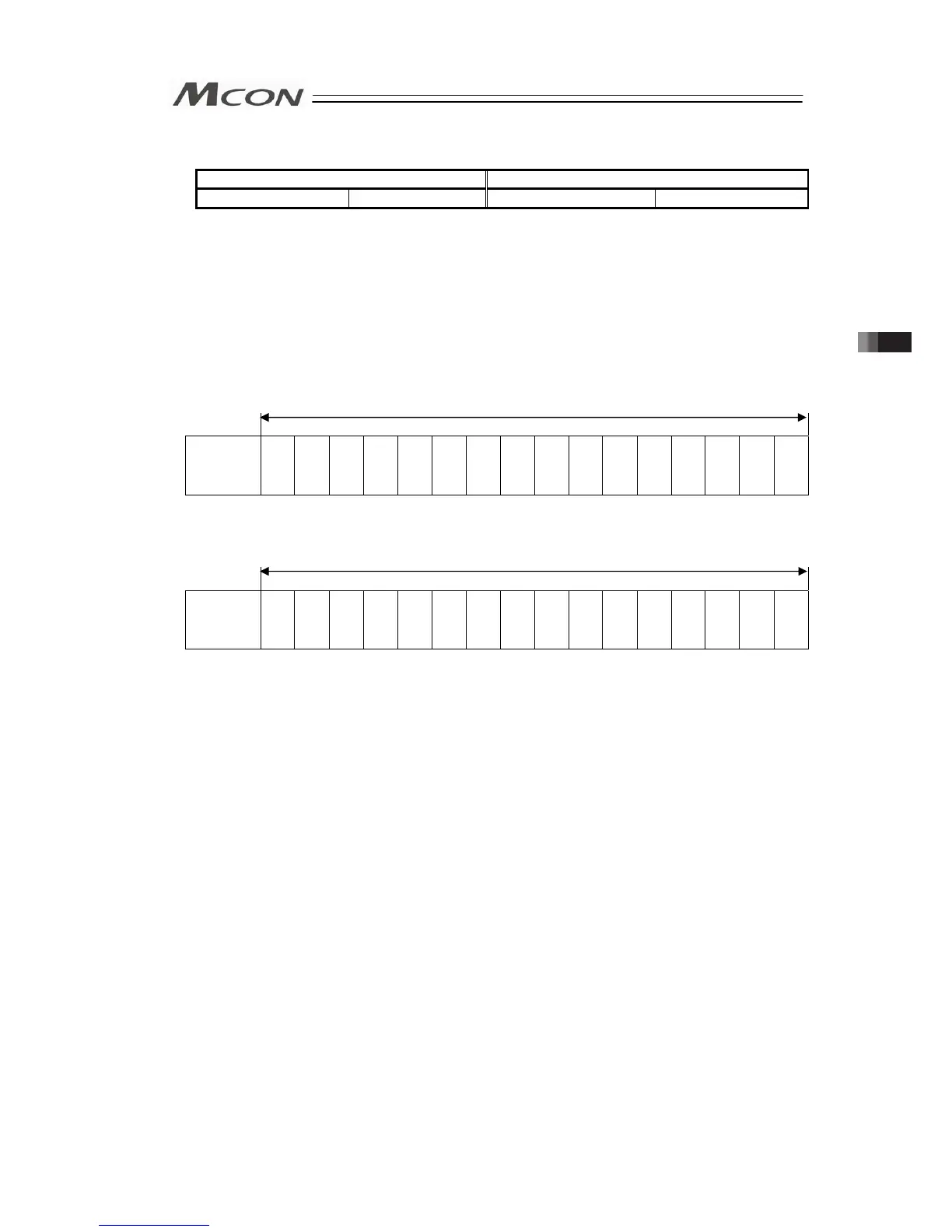
(2) Input and Output Signal Assignment for each Axis
The I/O signals for each axis consists of 1 word for each I/O bit register.
● The I/O bit register is controlled using the ON/OFF signal in units of bit.
(ON = Applicable bit is “1”, OFF = Applicable bit is “0”)
● The content of the signal for each bit changes depending what is selected in the PIO
patterns.
[Refer to next section I/O signal assignment]
PLC Output (m is PLC input and output top word address for each axis number)
Address m
b15 b14 b13 b12 b11 b10 b9 b8 b7 b6 b5 b4 b3 b2 b1 b0
Controller
Input port
No.
15
14
13
12
11
10
9
8
7
6
5
4
3
2
1
0
PLC Input (m is PLC input and output top word address for each axis number)
Address m
b15 b14 b13 b12 b11 b10 b9 b8 b7 b6 b5 b4 b3 b2 b1 b0
Controller
Output Port
No.
15
14
13
12
11
10
9
8
7
6
5
4
3
2
1
0
1 word=16 bit
1 word=16 bit
3.4 Fieldbus Type Address Map