287
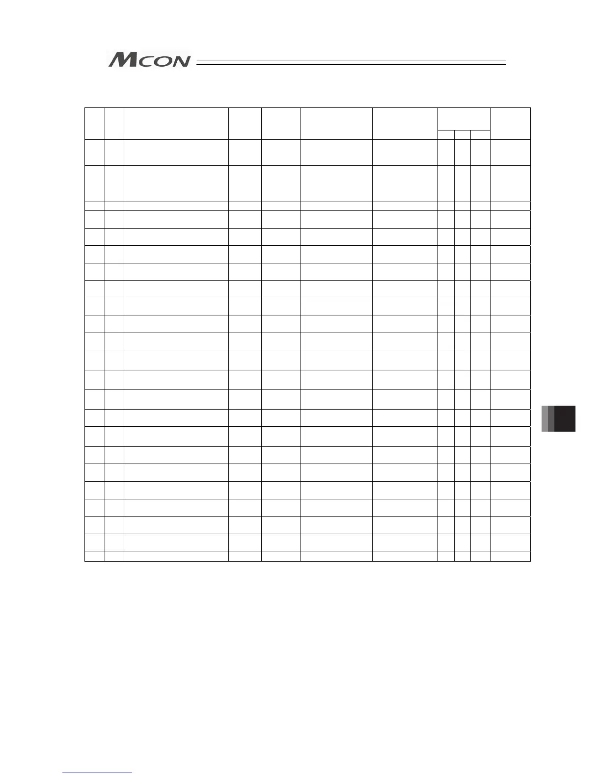
Parameter List (4/5)
Applicable
Motor Type
(Note 3)
No.
Category
Name Symbol Unit
(Note 1)
Input Range
Default factory
setting
A P D
Relevant
sections
110 B Stop Method at Servo OFF PSOF -
0: Rapid stop
1: Deceleration to
stop
0 ○ ○ ○ 8.2 [52]
112 B
Monitoring Mode Selection
Monitoring Period
FMNT
-
0: Unused
1:
Monitor Function 1
2:
Monitor Function 2
3:
Monitor Function 3
1 ○ ○ ○ 8.2 [53]
113 B Monitoring Period FMNT msec 1 to 60000 1 ○ ○ ○ 8.2 [54]
120 C Servo Gain Number 1 PLG1 - 0 to 31
In accordance
with actuator
(Note 2)
○
- -
8.2 [55]
8.2 [5]
121 C Feed Forward Gain 1 PLF1 - 0 to 100
In accordance
with actuator
(Note 2)
○
- -
8.2 [55]
8.2 [47]
122 C
Velocity Loop Proportional
Gain 1
VLG1 - 1 to 27661
In accordance
with actuator
(Note 2)
○
- -
8.2 [55]
8.2 [23]
123 C Velocity Loop Integral Gain 1 VLT1 - 1 to 217270
In accordance
with actuator
(Note 2)
○
- -
8.2 [55]
8.2 [24]
124 C Torque Filter Time Constant 1 TRF1 - 0 to 2500
In accordance
with actuator
(Note 2)
○
- -
8.2 [55]
8.2 [25]
125 C
Current Control Width
Number 1
CLP1 - 0 to 15
In accordance
with actuator
(Note 2)
○
- -
8.2 [55]
8.2 [39]
126 C Servo Gain Number 2 PLG2 - 0 to 31
In accordance
with actuator
(Note 2)
○
- -
8.2 [55]
8.2 [5]
127 C Feed Forward Gain 2 PLF2 - 0 to 100
In accordance
with actuator
(Note 2)
○
- -
8.2 [55]
8.2 [47]
128 C
Speed Loop Proportional
Gain 2
VLG2 - 1 to 27661
In accordance
with actuator
(Note 2)
○
- -
8.2 [55]
8.2 [23]
129 C Speed Loop Integral Gain 2 VLT2 - 1 to 217270
In accordance
with actuator
(Note 2)
○
- -
8.2 [55]
8.2 [24]
130 C Torque Filter Time Constant 2 TRF2 - 0 to 2500
In accordance
with actuator
(Note 2)
○
- -
8.2 [55]
8.2 [25]
131 C
Current Control Width
Number 2
CLP2 0 to 15
In accordance
with actuator
(Note 2)
○
- -
8.2 [55]
8.2 [39]
132 C Servo Gain Number 3 PLG3 - 0 to 31
In accordance
with actuator
(Note 2)
○
- -
8.2 [55]
8.2 [5]
133 C Feed Forward Gain 3 PLF3 - 0 to 100
In accordance
with actuator
(Note 2)
○
- -
8.2 [55]
8.2 [47]
134 C
Speed Loop Proportional
Gain 3
VLG3 - 1 to 27661
In accordance
with actuator
(Note 2)
○
- -
8.2 [55]
8.2 [23]
135 C Speed Loop Integral Gain 3 VLT3 - 1 to 217270
In accordance
with actuator
(Note 2)
○
- -
8.2 [55]
8.2 [24]
136 C Torque Filter Time Constant 3 TRF3 - 0 to 2500
In accordance
with actuator
(Note 2)
○
- -
8.2 [55]
8.2 [25]
137 C
Current Control Width
Number 3
CLP3 - 0 to 15
In accordance
with actuator
(Note 2)
○
- -
8.2 [55]
8.2 [39]
138 C
Servo Gain Switchover Time
Constant
GCFT ms 10 to 2000 10 ○ - - 8.2 [56]
143 B Overload Level Ratio OLWL % 50 to 100
- ○ - ○ 8.2 [57]
Note 1 The unit [deg] is for rotary actuator and lever type gripper. It is displayed in [mm] in the teaching tools.
Note 2 The setting values vary in accordance with the specification of the actuator. At shipment, the
parameters are set in accordance with the specification.
Note 3
A: Servo motor type, P: Pulse motor type, D: Brushless DC Motor
Chapter 8 Parameter

 Loading...


