45
[7] Wiring Layout for Fieldbus
Follow the instruction manual of the master unit for each Fieldbus and the constructing PLC for
the details of how to connect the cables.
1) DeviceNet Type
Slave Devices
MCON-DeviceNet Type
V+
Drain
(Shield)
CAN_H
CAN_L
V-
RD
WT
BL
BK
RD
WT
BL
BK
V+
Drain
(Shield)
CAN_H
CAN_L
Class D grounding
(Formerly Class-III grounding: Grounding resistance at 100
Ω
or less)
V+
Drain
(Shield)
CAN_H
CAN_L
V-
RD
WT
BL
BK
Communication power needs to be
supplied by an external device.
Terminal Resistance is required
to be mounted on the terminal.
V-
Terminal Resistance
121
Ω
Master Unit
Terminal Resistance
121
Ω
24V
Power Supply
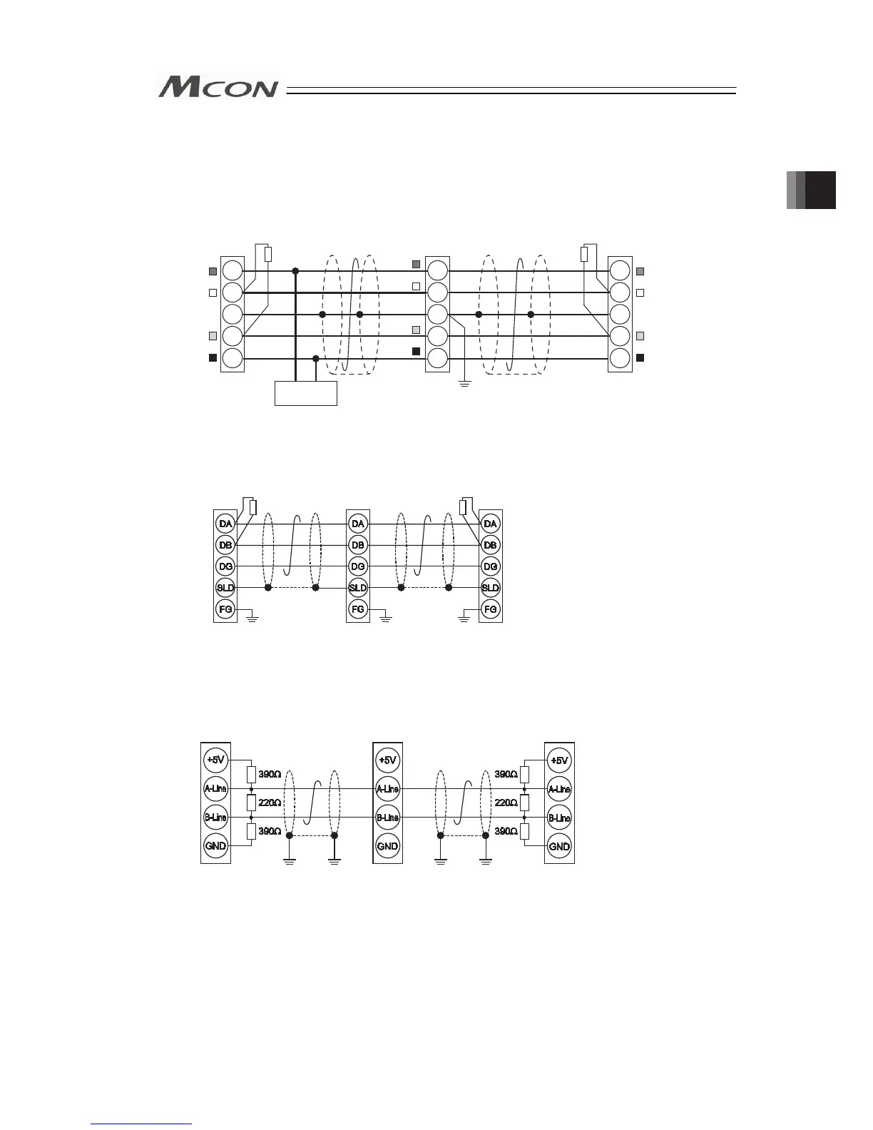
2) CC-Link Type
Slave Devices
MCON-
CC-Link
Type
SLD and FG are internally connected.
Terminal Resistance is required
to be mounted on the terminal.
The terminal resistor differs depending on the type
of the dedicated cable for CC-Link.
• Cable FANC-SBH···130
Ω
1/2W
(High Performance Cable
dedicated for CC-Link)
• Cable FANC-SB······110
Ω
1/2W
(CC-Link Dedicated Cable)
Master Unit
Terminal
Resistance
Terminal
Resistance
Class D grounding
(Formerly Class-III grounding:
Grounding resistance at 100
Ω
or less)
3) PROFIBUS-DP Type
MCON-PROFIBUS Type
Slave Devices
Master Unit
Terminal Resistance is required
to be mounted on the terminal.
Class D grounding
(Formerly Class-III grounding: Grounding resistance at 100
Ω
or less)
Chapter 2 Wiring