EasyManua.ls Logo

IAI MCON-C - Page 54

IAI MCON-C
480 pages
To Next Page IconTo Next Page
To Previous Page IconTo Previous Page
Loading...
44
[5] Layout for External Brake Input Circuit
Lay out the circuit when an external compulsory brake release with using an actuator equipped
with a brake is desired. It is not necessary if an external release is not required.
The brake can be released if the power (24V DC, 150mA/axis) gets supplied to this connector
even without the main power source supplied from the controller.
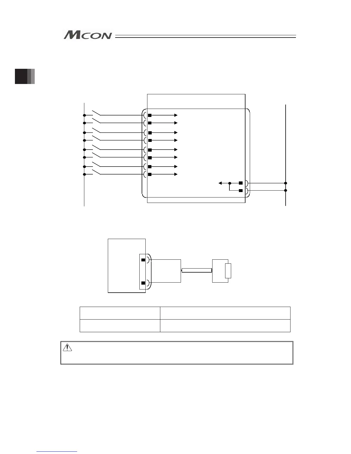
[6] Layout of Regenerative Resistor (Option)
Condition to Require Regenerative Units
Number of Connected Actuator 3 to 8 units of high acceleration/deceleration type
actuators
Number of Regenerative
Resistor Unit
1
Caution: The regenerative resistor consumes regenerative current and converts it to heat.
Therefore, the temperature may get high in some operational conditions.
Attach on the metal part of the device with a screw the heat.
A
xis No.0 Brake Release Input Circuit
A
xis No.7 Brake Release Input Circuit
A
xis No.6 Brake Release Input Circuit
A
xis No.4 Brake Release Input Circuit
A
xis No.5 Brake Release Input Circuit
A
xis No.3 Brake Release Input Circuit
A
xis No.2 Brake Release Input Circuit
A
xis No.1 Brake Release Input Circuit
MCON
GND for Brake Release
BKRLS AXIS No.3
BKRLS AXIS No.0
BKRLS AXIS No.2
0V
0V
BKRLS AXIS No.5
BKRLS AXIS No.1
BKRLS AXIS No.4
BKRLS AXIS No.7
BKRLS AXIS No.6
24V
0V
External Brake Input Connector
MCON
RB-
RB+
System I/O
Connector
External Regenerative
Resistor Units
(
RER-1
)
4
3
2
1
9
8
7
6
5
10
7
8
Chapter 2 Wiring

Table of Contents

Other manuals for IAI MCON-C

Related product manuals