ecification
[2] Read response command data 0 to 3
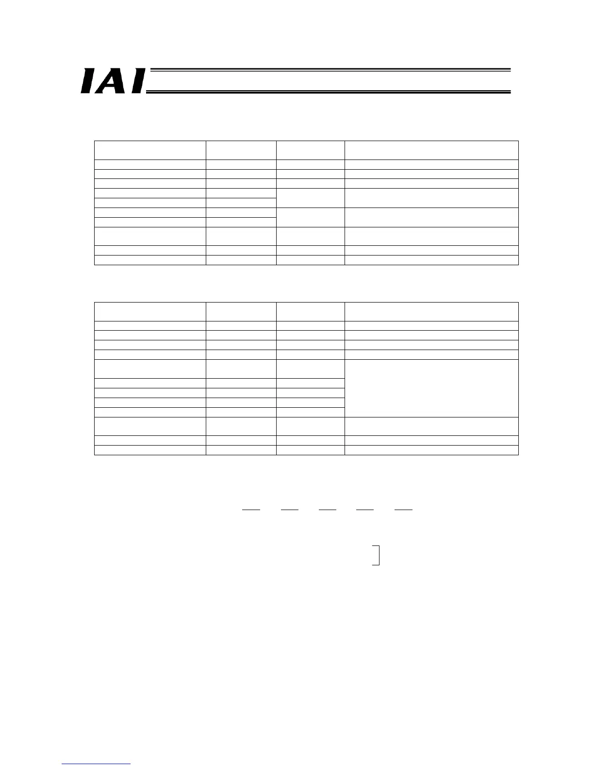
z Query
Field name
RTU mode data
(8 bits)
Data length
(bytes)
Remarks
Header None -
Slave address 3F H 1 Fixed.
Function code 03 H 1
Starting address (upper) F7 H
Starting address (lower) 02 H
2 Initial address of the response command
Number of registers (upper) 00 H
Number of registers (lower) 05 H
2 Number of registers (1 register = 1 word): 5
Error check (CRC)
Based on
calculation result
2 (12 A3)
Trailer None -
Total bytes 8
z Response
Field name
RTU mode data
(8 bits)
Data length
(bytes)
Remarks
Header None -
Slave address 3F H 1 Fixed.
Function code 03 H 1
Data bytes 0A H 1 1-word register x 5 = 10 bytes
Data 1 (upper) (lower)
Response
command
2
Data 2 (upper) (lower) Data 0 2
Data 3 (upper) (lower) Data 1 2
Data 4 (upper) (lower) Data 2 2
Position number specified in the request
command
Data 5 (upper) (lower) Data 3 2 Address
Error check (CRC)
Based on
calculation result
2
Trailer None -
Total bytes
z Actual Example (Example of reading the response data after issuing a command to read the table position for position
No. 2 of axis 0)
Sent Query: 3F03F702000512A3
Received Response: 3F030A 1040
0002 2710 0000 0000 A74A
[1] [2] [3] [4] [5]
(Explanation) [1] The response command is “1040H,” meaning that this is a target position read command.
[2] Position number: 2
[3] Lower word of position data that has been read: 2710H
[4] Upper word of position data that has been read: 0000H
[5] Axis number: 0
2710H = 10000 (decimal)
→ 100.00 mm

 Loading...


