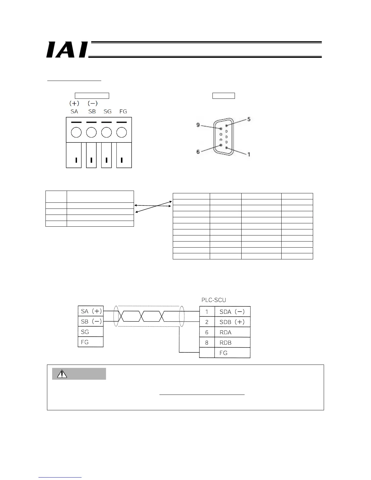
(4) RS485SIO
Using the 2-wire method, connect the GateWayR unit (RGW-SIO) to the RS-422A/485 port on the serial communication unit
(SCU) of the PLC, as shown below.
GateWayR unit PLC-SCU
Signal
name
Explanation
SA Communication line A (+)
SB Communication line B (-)
SG Signal ground
FG Frame ground
Use a shielded twisted pair cable (AWG28-16) for the communication cable.
Caution
1. The polarities of corresponding pins are reversed on the ROBONET end and PLC end of the communication line.
When connecting the ROBONET and PLC, connect the pins of the same polarities
.
SA (+) on GateWayR
⇔ SDB (+) on SCU, SB (-) on GateWayR ⇔ SDA (-) on SCU,
2. Connect the shield to ground only on the PLC-SCU end.
RS-422A/485 connector
Cable connector (supplied)
MC1.5/4-ST-3.5 (manufactured by
Phoenix Contact)
(D-sub 9-pin male connector as
viewed from the soldered side)
Connector pin arrangements
Pin No. Abbreviation Signal name Input/output
1 *1 SDA Send data - Output
2 *1 SDB Send data + Output
3 NC Not used -
4 NC Not used -
5 NC Not used -
6 *1 RDA Receive data - Input
7 NC Not used -
8 *1 RDB Receive data + Input
9 NC Not used -
Shell *2 FG Shield -
*1 For 2-wire connection, use pins 1 and 2, or pins 6 and 8.
*2 The shell is connected to the ground terminal (GR) of the
power-supply unit through the SCU. Accordingly, the shield
will be grounded when the GR of the power-supply unit is
connected to ground.
GateWayR unit
Shield
Shell

 Loading...


