ecification
2.3 General Specifications
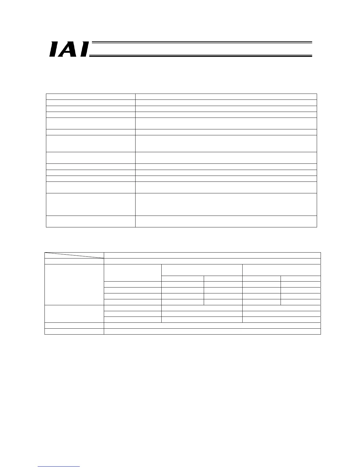
The general specifications of a ROBONET system are listed below.
Item Specification
Power-supply voltage
24 VDC ± 10 %
Power-supply current Varies depending on the system configuration.
Maximum number of connectable axes 16 axes (Controller units can be combined freely.)
Supported field networks CC-Link, DeviceNet, PROFIBUS, RS485 SIO
(slave station)
ROBONET communication protocol Modbus protocol
Component units GateWayR unit, controller unit, simple absolute R unit
ROBONET extension
(Refer to 2.2 for details.)
Emergency stop/enable operation The entire system is stopped by the emergency stop input from the GateWayR
unit. Each controller unit has a built-in drive-source cutoff relay.
Surrounding air temperature
0 to 40°C
Surrounding humidity 95% RH max. (non-condensing)
Protection degree IP20
External dimensions of each unit 34 W x 105 H x 73.3 D [mm]
All units have the same dimensions.
Interconnection of units Power-supply connection plate
Unit link cable or controller connection cable when the ROBONET communication
connection circuit board, simple absolute connection circuit board or ROBONET
extension unit is used (multi-stage layout or external SIO link)
Installation method Installation on a DIN rail (35 mm)
(However, controllers corresponding to external SIO link axes are excluded.)
2.4 24-V Power Current Consumption of Each Unit
Current consumption
GateWayR unit 600 mA max. (Common to all four types)
Standard specification, high
acceleration/deceleration type
Energy-saving type
Actuator
Rating Max. *1 Rating Max. *1
SA3 (10) 1.3 A 4.0 A 1.3 A 2.2 A
SA4ySA5yRA4 (20) 1.3 A 4.4 A 1.3 A 2.5 A
SA6yRA4 (30) 1.3 A 4.0 A 1.3 A 2.2 A
RACON unit
RA3 (20S) 1.7 A 5.1 A 1.7 A 3.4 A
Actuator Rating Max. *2
20P, 28P, 28SP motors 0.4 A 2.0 A
RPCON unit
42P, 56P motors 1.2 A 2.0 A
Simple absolute R unit 300 mA max.
ROBONET extension 100 mA max.
*1 The current becomes the maximum during the excited-phase detection of the servo motor performed when the servo is
turned on for the first time following the power on. (Normal: Approx. 1 to 2 seconds, Maximum: 10 seconds)
*2 The current becomes the maximum during the excited-phase detection performed when the servo is turned on for the first
time following the power on. (Normal: 100 msec)

 Loading...


