ecification
6.4 Name of Each Part and External Dimensions
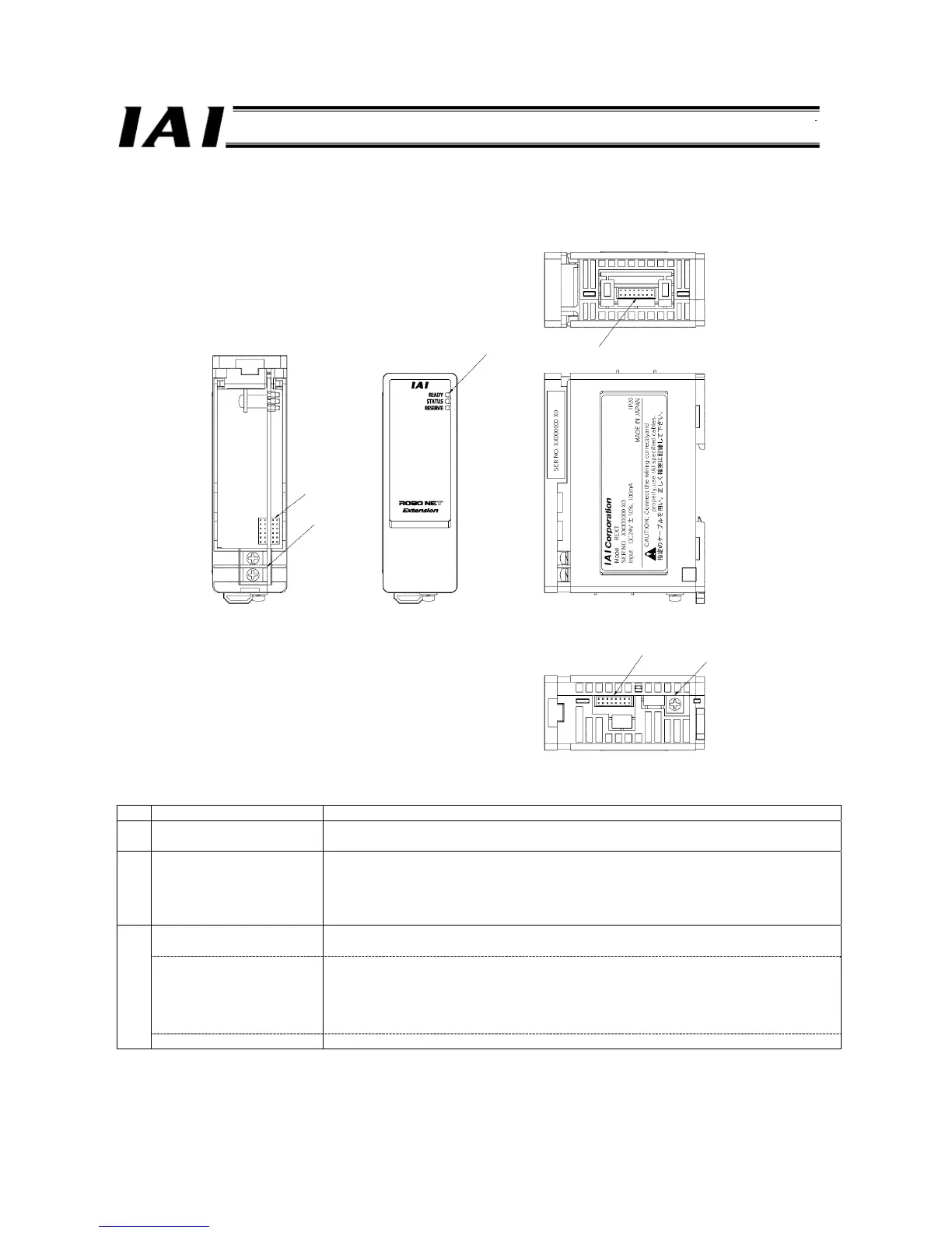
6.4.1 Name of Each Part
No. Name Description
[1]
ROBONET communication
connector
This communication connector is used to connect a unit in the same row (same stage).
It is connected using a ROBONET communication connection circuit board (JB-1).
[2]
Power-supply terminal block These are 24-VDC input terminals for the unit. The top terminal is +24 V, while the bottom
terminal is 0 V. To connect a power-supply wire, use a M3 round terminal of 6 mm or less
in width.
Connection with a unit in the same row (same stage) uses a power-supply connection
plate (PP-1).
Indicator LEDs
READY
This LED indicates the status of the internal power supply (5 V) of the unit.
• Green light: Normal • Unlit: Internal power supply error
STATUS This LED indicates the connection statuses of connectors [4] and [5].
• Green light: Normal (Only one connector is connected.)
• Red light: Abnormal (Both connectors are connected.)
• Unlit: Abnormal (Neither connector is connected.)
When used in the external SIO link connection, this LED is unlit.
[3]
RESERVE This LED is not used and remains unlit at all times.
[1]
[2]
[3]
[4]
[5]
[6]

 Loading...


