ecification
(3) Data Area Configuration in the Direct Numerical Specification Mode
PLC output ⇒ Axis input
Axis output ⇒ PLC input
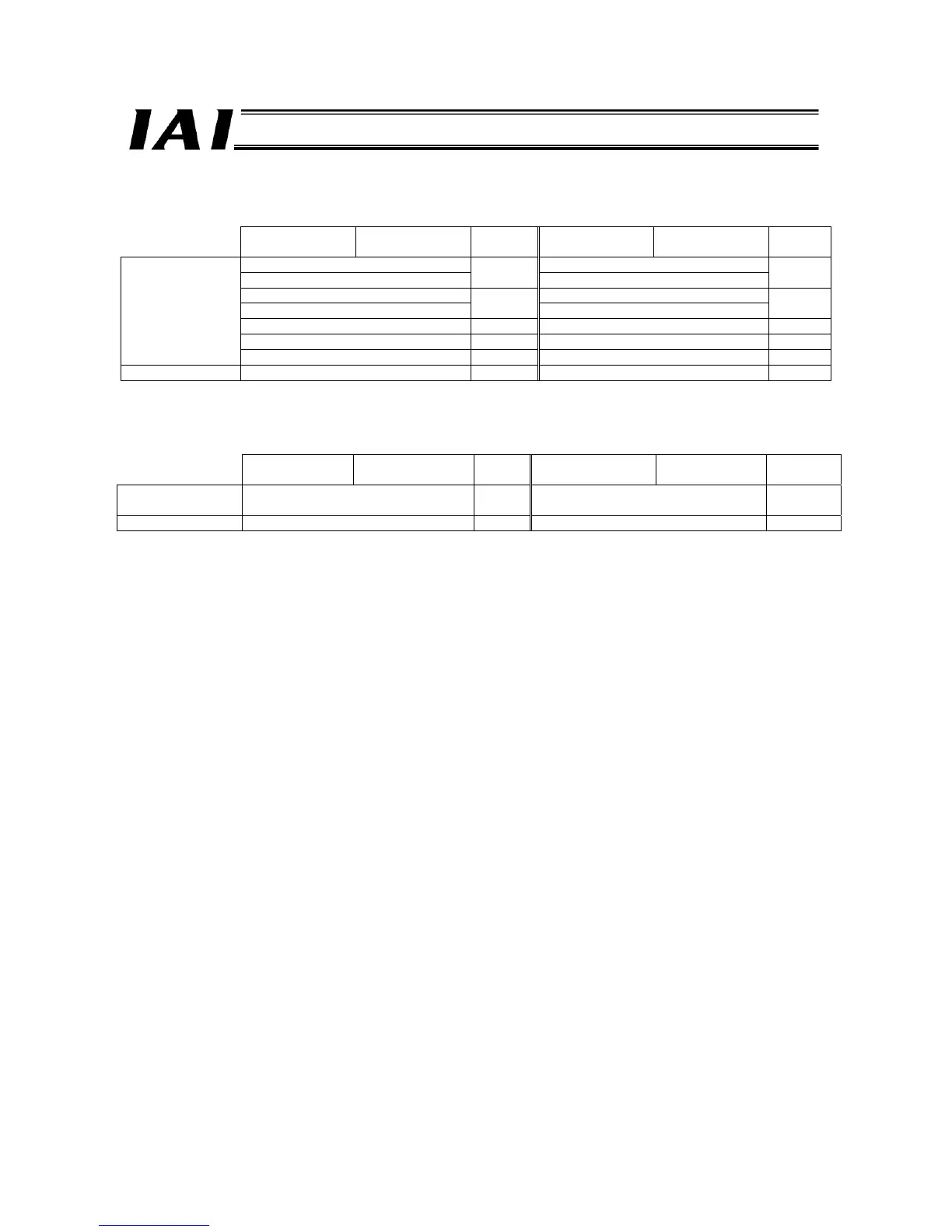
Upper byte Lower byte
Number
of words
Upper byte Lower byte
Number
of words
Position data specification (L)* Current position data (L)*
Position data specification (H)*
2
Current position data (H)*
2
Positioning band specification (L)* Current electrical current (L)*
Positioning band specification (H)*
2
Current electrical current (H)*
2
Speed specification 1 Current speed data 1
Acceleration/deceleration specification 1 Cannot be used. 1
Direct numerical
specification area
Push-current limiting value 1 Alarm code 1
Control signal area Control signal 1 Status signal 1
* (L) indicates the lower word of 2-word data, while (H) indicates the upper word of 2-word data.
(4) Data Area Configuration in the Position 2 Mode, Solenoid valve mode 1 And Solenoid Valve 2 Mode
Upper byte Lower byte
Number
of words
Upper byte Lower byte
Number of
words
Position
specification area
Command position number
1
Completed position number
1
Control signal area Control signal 1 Status signal 1
3.7.1 Examples of Overall Address Configuration
Overall address configurations are shown based on a system where 12 4-word mode axes (positioner 1/simple direct mode)
and two 8-word mode axes (direct numerical specification mode) are connected.
For your information, the CC-Link and DeviceNet types use word addressing, while the PROFIBUS and RS485 SIO types use
byte addressing.
(1) CC-Link
A configuration example using the CC-Link type is shown on the next page.
The eight words in the fixed area are assigned to bit registers (RX/RY), while the area of each axis is assigned to word
registers (RWr/RWw).

 Loading...


