ecification
PROFIBUS
Position data specification(Signed integer)
PLC output = Axis control signal
Position data specification(Signed integer)
Command position Number
Control signal
BKRL
MODE
PWRT
JOG +
JOG
-
PC512
PC256
PC128
PC64
PC32
PC16
PC8
PC4
PC2
PC1
JVEL
JISL
SON
RES
STP
HOME
CSTR
1 word = 18 bits
b15 b14 b13 b12 b11 b10 b9 b8 b7 b6 b5 b4 b3 b2 b1 b0
Address*
(Upper byte)
(Lower byte)
RS485SIO
CC-Link DeviceNet
RWw (m+0) n+0
RWw (m+1) n+1
RWw (m+2) n+2
RWw (m+3) n+3
n+0
n+1
n+2
n+3
n+4
n+5
n+6
n+7
PROFIBUS
Current position data(Signed integer)
Current position data(Signed integer)
PLC input = Axis status signal
Completed position Number
Status signal
EMGS
CRDY
ZONE2
ZONE1
PZONE
MODES
WEND
PM512
PM256
PM128
PM64
PM32
PM16
PM8
PM4
PM2
PM1
PSFL
SV
ALM
MOVE
HEND
PEND
b15 b14 b13 b12 b11 b10 b9 b8 b7 b6 b5 b4 b3 b2 b1 b0
Address*
(Upper byte)
(Lower byte)
RS485SIO
CC-Link DeviceNet
RWw (m+0) n+0
RWw (m+1) n+1
RWw (m+2) n+2
RWw (m+3) n+3
n+0
n+1
n+2
n+3
n+4
n+5
n+6
n+7
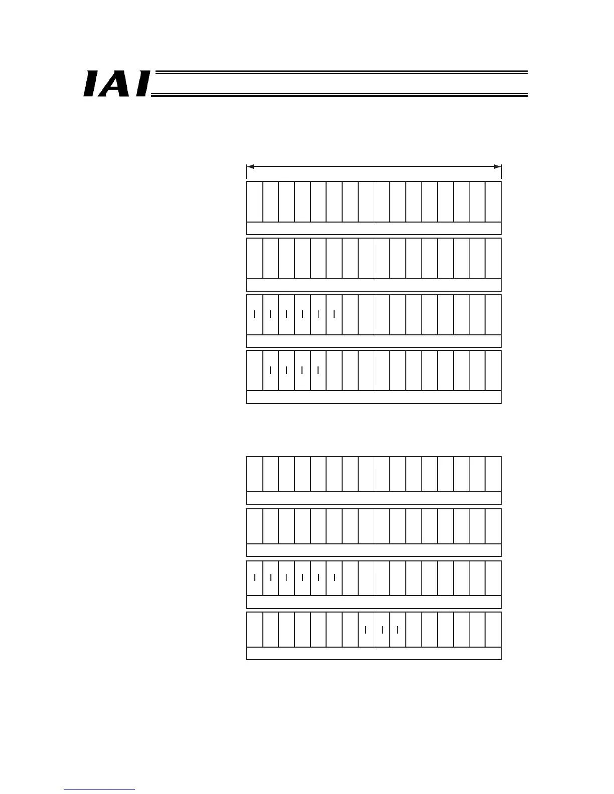
3.7.5 Assignments in the Positioner 1 Mode or Simple Direct Mode
Assignments in the positioner 1 mode or simple direct mode are shown below.
* m indicates the initial register address of each axis.
n indicates the relative address at the beginning of each address.
The CC-Link and DeviceNet types use word addresses, while the PROFIBUS and RS485 SIO types use byte addresses.

 Loading...


