ecification
3.5.3 MODE Switch
This switch is used to set the operation mode of the controller.
Status Explanation
MANU Manual operation: The ROBONET system can be operated using a teaching pendant or PC.
AUTO Auto operation: The ROBONET system is controlled via field network communication.
3.5.4 TP Connector
This connector is dedicated for a use of connecting a teaching pendant or a PC cable.
Connector: TCS7587-0121077 (by Hosiden)
3.5.5 User Setting Switches
These switches are used to set the operation mode of the GateWayR unit.
Normally SW3 and SW4 should remain OFF (they should be in the left positions). Do not change the settings of these
switches.
Explanation
SW No.
CC-Link DeviceNet PROFIBUS RS485SIO
SW4 Always OFF
SW3 Always OFF
SW2 Always OFF Endian *2
ON: SIO through mode
OFF: Modbus gateway mode
SW1 When this switch is set to ON, the TP enable switch signal is effective.
*1 SW1 to SW4 are ON when set to the right side, and OFF when set to the left side.
*2 Remote I/O endian
ON Little endian (LSB first) PLC by Mitsubishi, Omron, etc.
OFF Big endian (MSB first) PLC by Siemens
3.5.6 ROBONET Communication Connector
This connector is used to connect a Modbus communication line, emergency stop signal, etc., to the axis controller unit.
Connection is made using the ROBONET communication connection circuit board supplied with the axis controller unit.
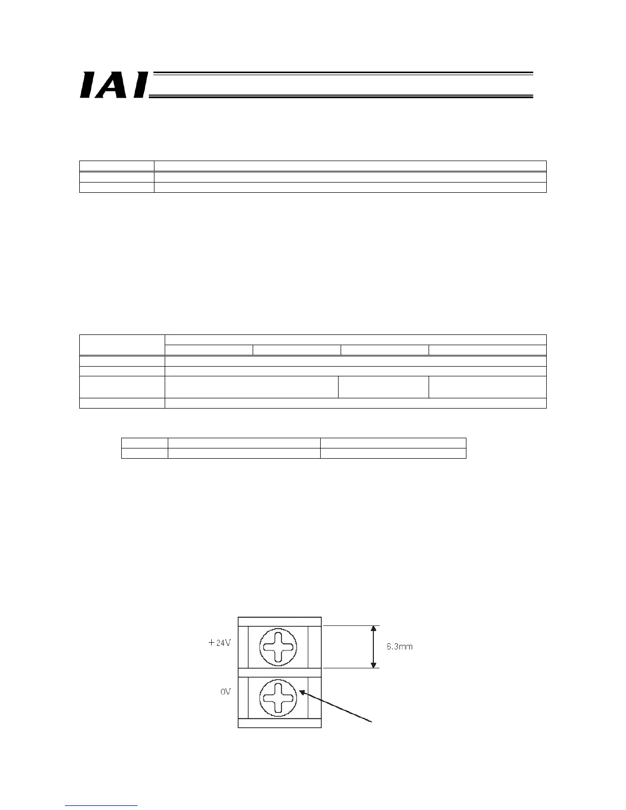
3.5.7 Power-supply Input Terminal Block
24-VDC power is input to this terminal block.
To supply power, connect the +24-V side and 0-V side to the power-supply input terminal block of the adjoining axis controller
unit using the power-supply connection plate supplied with the controller.
11. M3 screw
M3 screw

 Loading...


