ecification
3.9 Modbus Gateway Mode of RS485 SIO
3.9.1 Overview
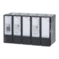
With the RS485 SIO GateWayR unit, the Modbus gateway mode
in which the unit operates as a Modbus/RTU slave station,
and the SIO through mode
in which the unit operates by means of serial communication per the Modbus/RTU and ASCII
protocols, are available.
For the operation in the SIO through mode, refer to the operation manual “ROBO CYLINDER Series – Serial Communication
(Modbus Version).”
This section explains the Modbus gateway mode.
Modbus/RTU is the only
applicable communication protocol in this mode, and the unit must be connected to a serial port that
supports the Modbus/RTU protocol.
Axes are operated by sending communication messages under the Modbus/RTU protocol to the GateWayR unit (RGW-SIO)
and accessing the gateway’s registers (addresses F600 onward and F700 onward in the PLC).
Normally communication messages must be created using a PLC ladder sequence. If the number of communications
increases, however, the required ladder sequence will become large and complex and creating an appropriate sequence will
require a longer time.
Accordingly, the “Modbus cyclic communication FBL
” is provided as a dedicated communication function block. This function
block is very useful because the user can use it to create a ladder sequence without a need to consider serial communication.
To use this function block, the PLC must meet the following conditions:
[1] CPU unit CS/CJ Series by Omron
(If the function block is to be used, the CS/CJ Series unit must be Version 4.0 or later
.)
[2] Serial communication unit CS/CJ Series by Omron
CS: CS1W-SCU**-V1 (Version 1.2 or later)
CJ: CS1W-SCU**-V1 (Version 1.2 or later)
[3] CX Programmer Version 7.0 or later
Caution
Switching of Modbus Gateway Mode and SIO Through Mode can be executed with the User Setting Switch (SW2) of
GateWayR unit.
SW2 ON : SIO Through Mode
OFF : Modbus Gateway Mode

 Loading...


