ecification
3.7.9 Assignment in Solenoid Valve Mode 2
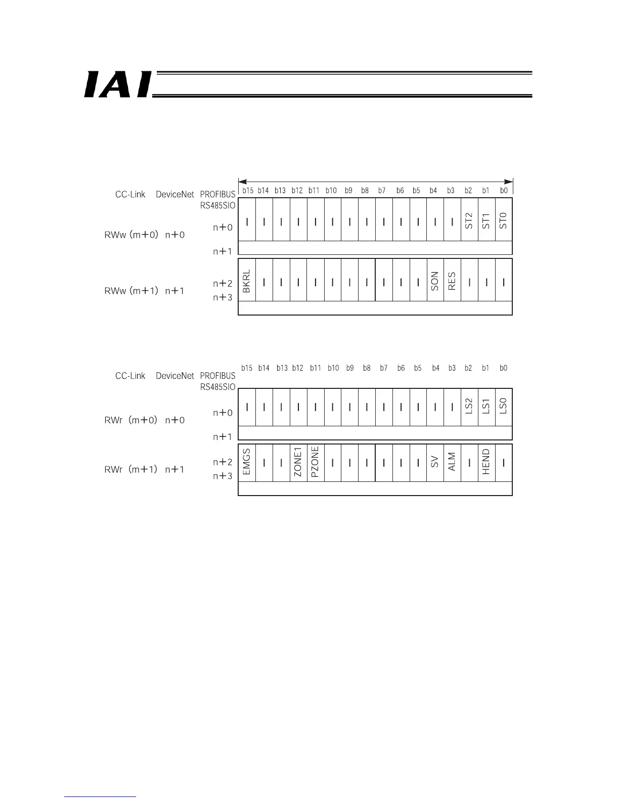
Assignment in the solenoid valve mode 2 is explained below.
PLC output = Axis control signal
PLC input = Axis status signal
* m indicates the initial register address of each axis.
n indicates the relative address at the beginning of each address.
The CC-Link and DeviceNet types use word addresses, while the PROFIBUS and RS485 SIO types use byte addresses.
(Upper byte)
(Lower byte)
1 word = 16 bits
Command position Number
Control signal
Address*
(Upper byte)
(Lower byte)
Completed position Number
Status signal
Address*

 Loading...


