(2) DeviceNet
Check the operation manual for the master (PLC) for details on DeviceNet. The following explains the points to note
regarding network wiring.
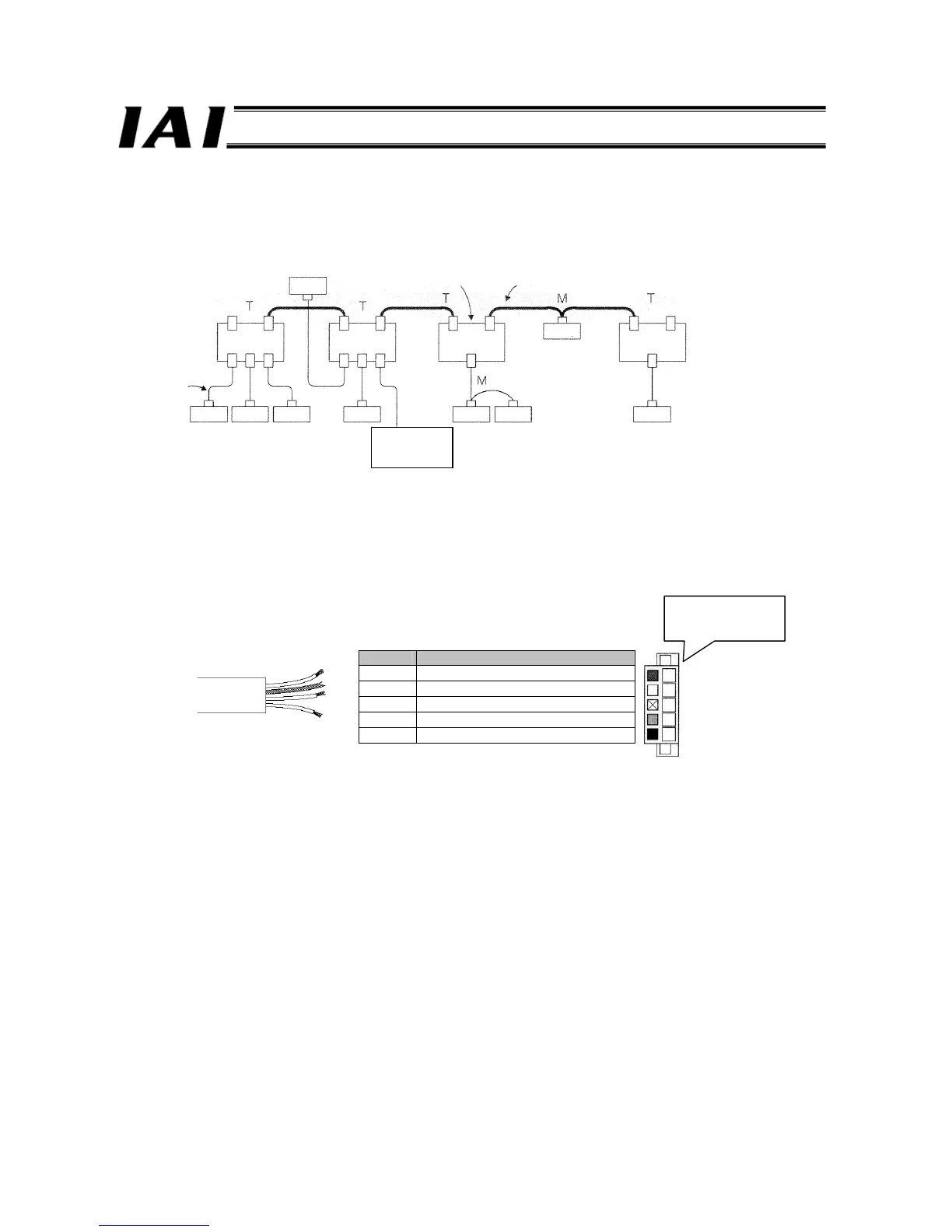
An example of network connection is shown below.
(1) An equipment connected to a network and having an assigned address is called a “node.” A node may be the master
(DeviceNet unit in the above figure) that manages the DeviceNet network, or a slave that connects external I/Os to the
network. Both master and slave nodes can be set in any positions.
(2) A terminal resistor is required on both ends of a trunk line (bold line in the figure). A cable branching from a trunk line
(normal line in the figure) is called a “branch line.”
Use a dedicated 5-wire cable for DeviceNet. Select a thick cable or thin cable according to the supplied current.
The dedicated cable is explained on the ODVA website.
The details of the dedicated cable are as follows.
Color Signal type
Red Power cable + (V+)
White Communication data high (CAN H)
--- Shield
Blue Communication data low (CAN L)
Black Power cable - (V-)
DeviceNet unit (master)
Node
T-branch tap
Trunk line
Node
Node
Node Node
Node
Node Node Node
Communication
power supply
24 VDC
With terminal
resistor
Branch
line
With terminal
resistor
Colors of wires are
also printed on the
dedicated connector.

 Loading...


