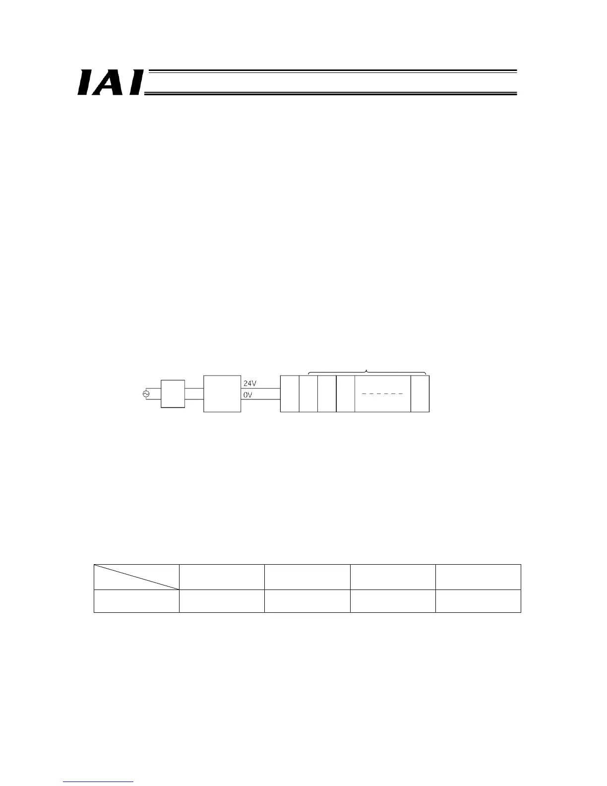
Circuit
breaker
Power supply
<Selection of Power-supply Capacity>
The method to select an appropriate 24-VDC power supply to be used with your ROBONET system is explained below.
(1) Current consumption of controller units when the respective axes operate simultaneously
Rated RACON current x Number of RACON controllers operating simultaneously (≥ 1) + Rated
RPCON current x Number of RPCON controllers operating simultaneously (≥ 1) --- [1]
(2) Current consumption of other units
= 0.6 A x Number of GateWayR units + 0.3 A x Number of simple absolute R units + 0.1 A x
Number of extension units --- [2]
The current consumption is calculated by [1] + [2] in a steady state.
(3) Current consumption during excited-phase detection
Maximum RACON current x Number of RACON controllers performing excited-phase detection simultaneously (≥ 1) +
Maximum RPCON current x Number of RPCON controllers performing excited-phase detection simultaneously (≥ 1)
--- [3]
Normally a power supply whose rated current is equivalent to ([1] + [2]) x 1.3 or more is selected by considering 20 to
30% of allowance in addition to the above current consumption of [1] + [2].
However, make sure you select a power supply of “peak load accommodation” specification or having a sufficient
allowance because the current of [3] will flow for a brief moment. Exercise special caution in the case that a remote
sensing function is equipped.
<Reference>
(1) It is recommended that the ROBONET power be turned on/off on the AC power supply side (primary side of the 24-V
power supply). If the ROBONET power is turned on/off on the output side of the 24-V power supply, the large current will
flow for a brief moment when the power is turned on, as explained in (2).
Turning on the power on the AC power supply side causes a rush current (*1) to flow where the size of this rush current is
determined by the 24-V power supply used. Accordingly, select a circuit breaker that will not trip when this rush current
flows.
(Example) If the PS241 is used as the 24-V power supply, a rush current of approx. 50 to 60 A will flow through the
power supply for approx. 3 ms. (Measured value)
*1 The specific value varies depending on the model of the 24-V power supply and impedance of the power-supply line.
(2) The table below lists the measured ROBONET rush currents (*2) that generate when the ROBONET power is turned
on/off on the DC side (secondary side of the 24-V power supply). (These values assume parallel connection of three
PS241s as 24-V power supplies.)
Number of axes
1 to 3 axes 4 to 8 axes 9 to 12 axes 13 to 16 axes
ROBONET rush
current
Approx. 50 to 60 A,
0.2 ms
Approx. 100 to 120 A,
0.2 to 0.5 ms
Approx. 120 to 130 A,
0.6 to 0.8 ms
Approx. 130 A
1.0 to 1.5 ms
*2 The specific ROBONET rush current varies depending on the model of the 24-V power supply and impedance of the
power-supply line. The values in the above table are reference values only and not guaranteed.

 Loading...


