iSeries Model 820
156 iSeries Handbook
Notes
Legend
Base Feature Required Feature
Unavailable if
Integrated xSeries
Server is installed
Note 1:
If C10 has an Integrated xSeries
Server, slot C09 is unavailable, and slot
C08 is available only as a short slot.
Note 2:
If C04 has an IntegratedxSeries
Server, slot C03 is not available, and slot
C02 is available only as a short slot.
Note 3
:
Position of the cards may change
depending on the console and other
features selected. A console is a
required feature.
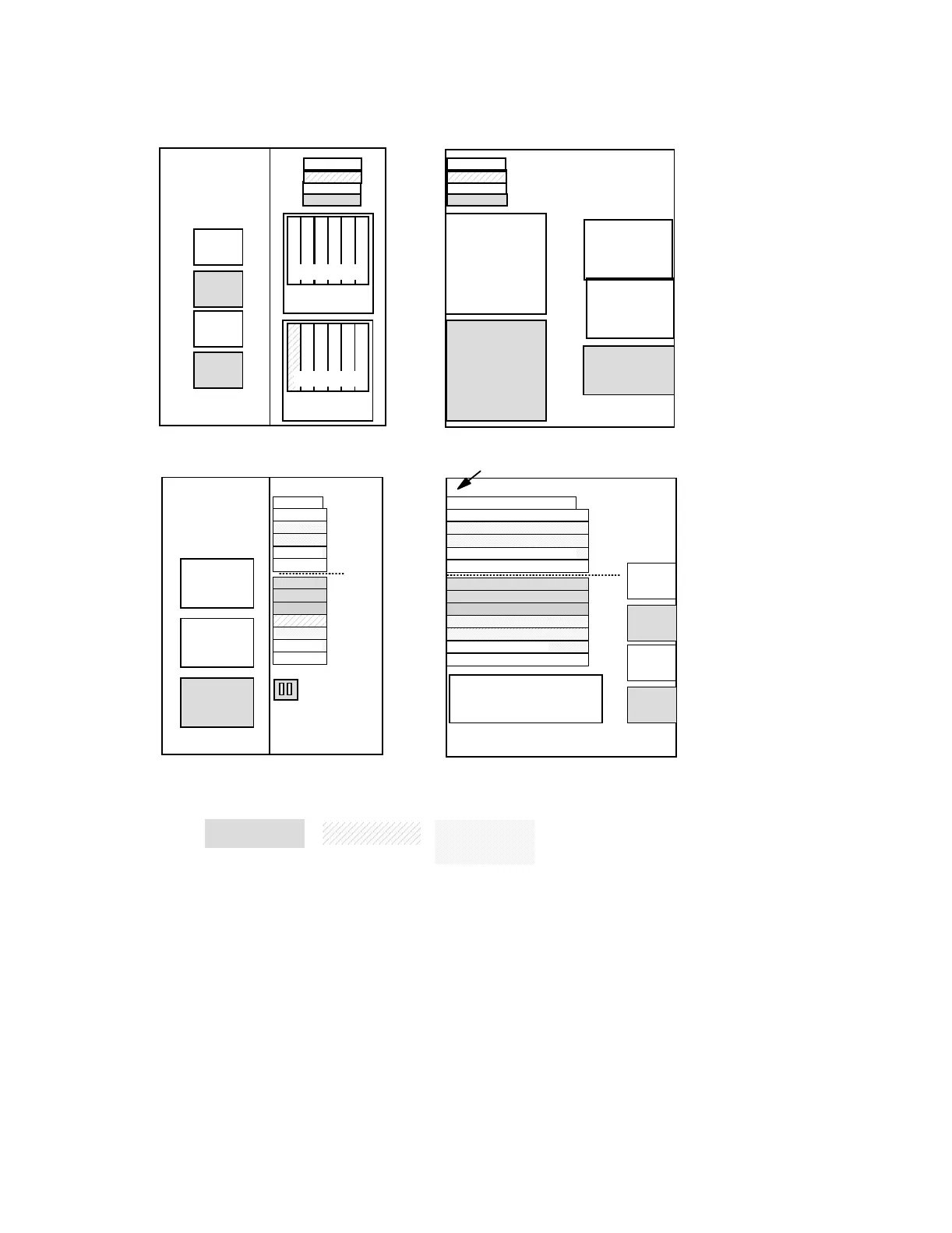
Back
Model 820 System Unit
Right
Disk Unit
Cage
DB1
Disk Unit
Cage
#7127
DB2
575W
Power Supply
PO1
#5157
575W
Power Supply
PO2
#5155
575W
Power Supply
PO3
Front
D13
D14
Fan
B03
Fan
B04
Fan
B01
Fan
B02
OP PanelOP Panel
OP Panel
OP PanelCD//DVD
Tape/CD/DVD
DISK SLOTS
D06
D05
D04
D03
D02
D01
DISK SLOTS
D12
D11
D10
D09
D08
D07
C11
EMBED
Slots
C10
C09
C12
C07
C08
C04
C02
C03
C06
C01
C05
DISK IOA
PCI
PCI
PCI
PCI
PCI
Short
PCI
PCI
PCI
PCI
IOP/IOA
PCI
PCI
575W
Power Supply
PO1
575W
Power Supply
PO2
575W
Power Supply
PO3
Note 1: Position of cards may change depending on the console and other features selected.
Left
Fan
B03
Fan
B04
Fan
B01
Fan
B02
3 DISK IOA
7,8 IOA
1 Embedded IOP
2 2-Line WAN w/Modem
PCI Cards
6 IOP/IOA
1 IOP S hort
2 IOA
3,4 IOP/IOA/Int xSeries Svr.
5 IOP/IOA
Multi-
Adapter
Bridge
Boundary
7 IOP/IOA
4 IDP/IDA/INS/Int xSeries Svr.
5,6 IOP/IOA
8 IOA
#
Multi-Adapter Bridge
Bus Number
C04
C02
C03
C11
C06
EMBED
C01
Slots
C10
C09
C12
C07
C08
C05
Processor and memory
layout on the following
page
HSL
1
1
1
1
2
2
3
3
Multi-
Adapter
Bridge
Boundary
OP Panel
CD/DVD
Tape/CD/DVD
short

 Loading...