17
OTHER FUNCTIONS
17-26
• DV RX call sign setting
Command : 20 0001, 20 0002
q Header flag data (First byte)
Data Description
bit7 (0: Fixed) —
bit6 (0: Fixed) —
bit5 (0: Fixed) —
bit4 0/1 0= Voice, 1= Data
bit3 0/1 0= Direct, 1= Through repeater
bit2 0/1 0= No Break-in, 1= Break-in
bit1 0/1 0= Data, 1= Control
bit0 0/1 0= Normal, 1= EMR
w Header flag data (Second byte)
Data
Description
bit2 bit1 bit0
1 1 1 Repeater control
1 1 0 Send auto acknowledge
1 0 1 (Not used)
1 0 0 Request to re-transmit
0 1 1 Send acknowledge
0 1 0 Receive no reply
0 0 1 Repeater disabled
0 0 0 NULL
e–!0: Call sign of the caller station (8 characters; fixed)
!1–!4: Note of the caller station (4 characters; fixed)
!5–@2: Call sign of the called station (8 characters; fixed)
@3–#0: Call sign of the access/area repeater (R1) (8 charac-
ters; fixed)
#1–#8: Call sign of the link/gateway repeater (R2) (8 charac-
ters; fixed)
• FF” stands for no call sign receiving after turning ON the
transceiver.
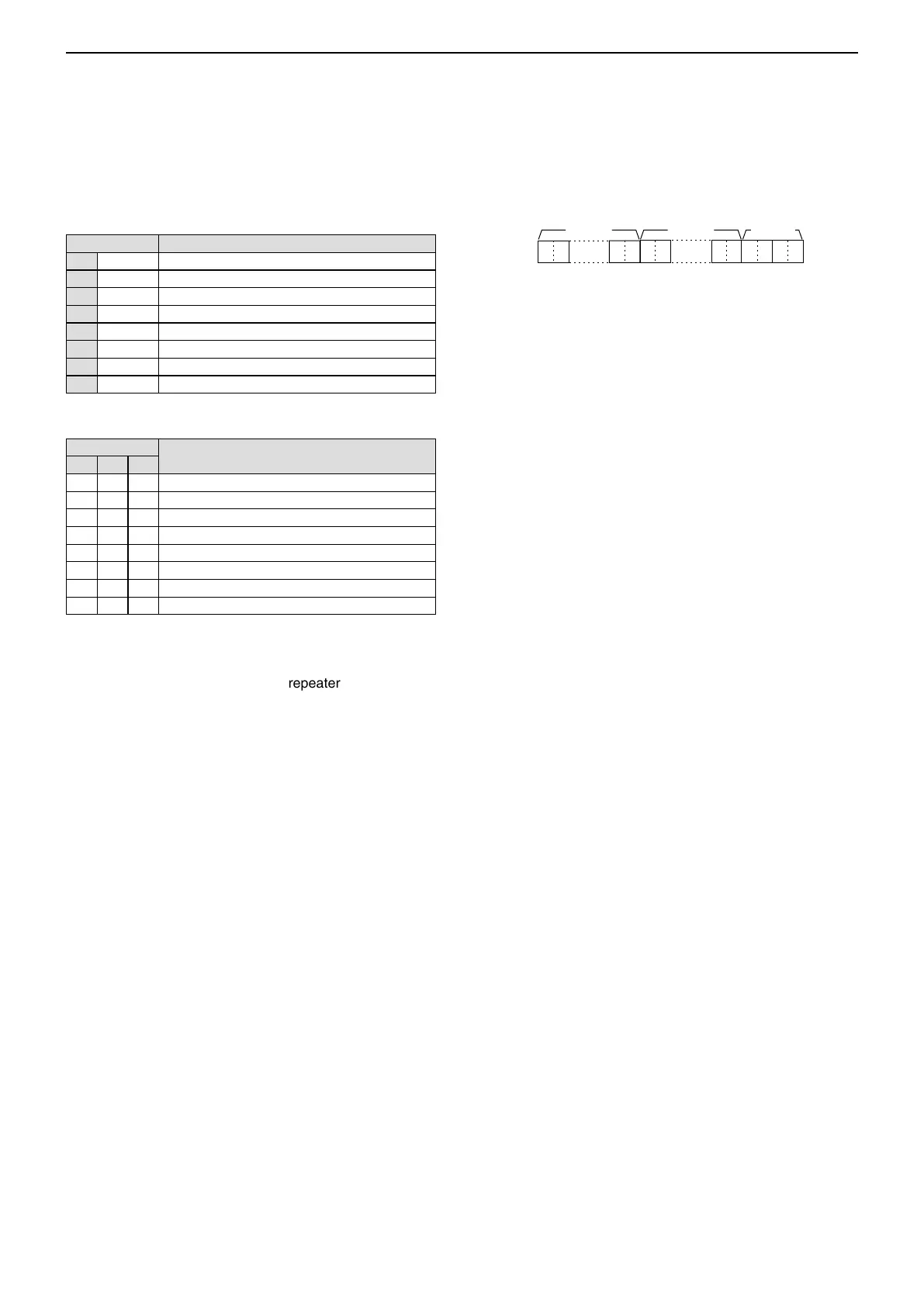
• DV RX message
Command: 20 0101, 20 0102
XX XXXXXX
@1–@8 @9–#2
• • •
XX
• • •
XX
q–@0
q–@0: Message (20 characters)
@1–@8: Call sign of the caller station (8 characters)
@9–#2: Note of the caller station (4 characters)
• FF: When no call sign is received since the transceiver pow-
er ON.
CI-V information (Continued) ■

 Loading...