Getting started with IDEC SmartRelay
IDEC SmartRelay Manual 13
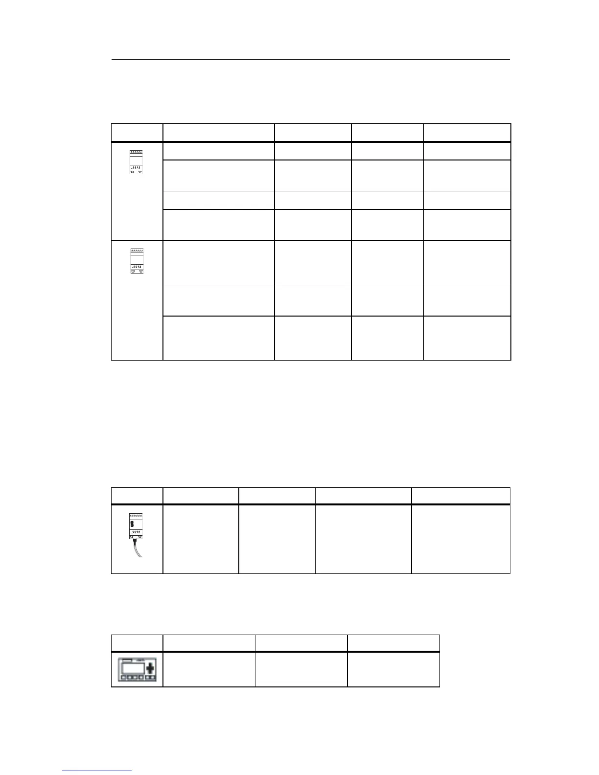
Expansion modules
The following expansion modules can be connected to IDEC
SmartRelay:
(1): Different phases are not allowed within the inputs.
(2): 0 ... 10 V, 0 ... 20 mA can be connected optionally.
(3): Digital inputs can be operated either with P or with N action.
(4): 0 ... 10 V, 0/4 ... 20 mA can be connected optionally.
Communication modules
The following communication modules can be connected
to IDEC
SmartRelay:
Text Display Module
The following Text Display module is available:
Symbol Name Power supply Inputs Outputs
FL1B-M08B2R2 12/24 V DC 4 digital 4 relays (5A)
FL1B-M08B1S2 24 V DC
4 digital 4 solid state 24V
/ 0.3A
FL1B-M08D2R2
(3)
24 V AC/DC 4 digital 4 relays (5A)
FL1B-M08C2R2 100...240 V
AC/DC
4 digital
(1)
4 relays (5A)
FL1B-J2B2 12/24 V DC 2 analog
0 ... 10V or
0 ... 20mA
(2)
none
FL1D-K2B2 24 V DC none 2 analog
0 ... 10 V DC
FL1D-K2BM2 24 V DC none 2 analog
0 ... 10 V DC,
0/4 ... 20 mA
(4)
Symbol Name Power supply Inputs Outputs
IDEC Smart-
Relay CM AS
Interface
30 V DC the
next four inputs
after the physical
inputs of IDEC
SmartRelay
(I
n
... I
n+3
)
the next four
outputs after the
physical outputs of
IDEC SmartRelay
(Q
n
... Q
n+3
)
Symbol Name Supply voltage Display
Text Display 24 V AC/DC
12 V DC
LCD (128 x 64)
4-row display
 Loading...
